Toyota Venza: Installation
INSTALLATION
PROCEDURE
1. INSTALL REAR COMBINATION LIGHT ASSEMBLY
|
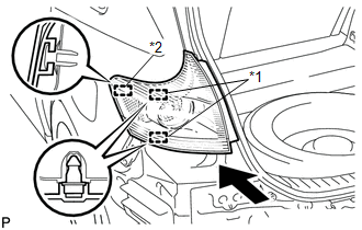
(a) Engage the guide and 2 pins, and install the rear combination light assembly as shown in the illustration. Text in Illustration
|
|
|
(b) Install the rear combination light assembly with the 2 nuts. Torque: 6.8 N·m {69 kgf·cm, 60 in·lbf} |
|
.png)
(c) Engage the clamp.
(d) Connect the connector.
2. INSTALL REAR BUMPER ASSEMBLY
.gif)
3. INSTALL REAR BUMPER PLATE LH
4. INSTALL REAR BUMPER PLATE RH
5. INSTALL DECK TRIM SIDE PANEL ASSEMBLY LH (for LH Side)
6. INSTALL DECK TRIM SIDE PANEL ASSEMBLY RH (for RH Side)
7. CONNECT REAR SEAT OUTER BELT ASSEMBLY
8. INSTALL LUGGAGE HOLD BELT STRIKER ASSEMBLY
9. INSTALL RECLINING REMOTE CONTROL BEZEL
10. INSTALL REAR SEAT ASSEMBLY LH (for LH Side)
11. CONNECT REAR SEAT NO. 2 RECLINING CONTROL CABLE SUB-ASSEMBLY (for LH Side)
12. INSTALL REAR SEAT OUTER TRACK BRACKET COVER (for LH Side)
13. INSTALL REAR SEAT INNER TRACK BRACKET COVER (for LH Side)
14. INSTALL REAR SEAT HEADREST ASSEMBLY (for LH Side)
15. INSTALL REAR SEAT ASSEMBLY RH (for RH Side)
16. CONNECT REAR SEAT RECLINING CONTROL CABLE SUB-ASSEMBLY (for RH Side)
17. INSTALL REAR SEAT OUTER TRACK BRACKET COVER (for RH Side)
18. INSTALL REAR SEAT INNER TRACK BRACKET COVER (for RH Side)
19. INSTALL REAR SEAT CENTER HEADREST ASSEMBLY (for RH Side)
20. INSTALL REAR SEAT HEADREST ASSEMBLY (for RH Side)
21. INSTALL REAR FLOOR FINISH PLATE
22. INSTALL REAR SEAT SUB FLOOR PANEL ASSEMBLY
23. INSTALL NO. 1 DECK BOARD
24. INSTALL DECK SIDE TRIM BOX LH
25. INSTALL NO. 3 DECK BOARD SUB-ASSEMBLY
26. INSTALL DECK SIDE TRIM BOX RH
27. INSTALL NO. 2 DECK BOARD SUB-ASSEMBLY
28. INSTALL DECK BOARD ASSEMBLY
29. INSTALL TONNEAU COVER ASSEMBLY (w/ Tonneau Cover)
30. CONNECT REAR DOOR OPENING TRIM WEATHERSTRIP
31. INSTALL REAR DOOR SCUFF PLATE
 Reassembly
REASSEMBLY
PROCEDURE
1. INSTALL REAR BUMPER UPPER RETAINER
(a) Engage the guide.
(b) Install the rear bumper upper retainer with the 2 scr ...
 Rear Light Assembly
Components
COMPONENTS
ILLUSTRATION
On-vehicle Inspection
ON-VEHICLE INSPECTION
PROCEDURE
1. INSPECT REAR LIGHT ASSEMBLY
(a) Disconnect the connector from the rear light assembl ...
Other materials about Toyota Venza:
Problem Symptoms Table
PROBLEM SYMPTOMS TABLE
HINT:
Use the table below to help determine the cause of problem symptoms. If multiple
suspected areas are listed, the potential causes of the symptoms are listed in order
of probability in the "Suspected Area" column of ...
Removal
REMOVAL
PROCEDURE
1. REMOVE FRONT WHEEL LH
2. REMOVE FRONT FENDER OUTSIDE MOULDING LH
3. REMOVE FRONT FENDER LINER LH
(a) Using a screwdriver, turn the pin 90 degrees and remove the 2 pin
hold clips.
Text in Illustration
...
Portable Player cannot be Registered
CAUTION / NOTICE / HINT
HINT:
Some versions of "Bluetooth" compatible audio players may not function properly,
or the functions may be limited using the navigation receiver assembly, even if
the portable audio player itself can play files (See ...

0.1338