Toyota Venza: Pressure Control Solenoid "G" Electrical (Shift Solenoid Valve SL4) (P2810)
DESCRIPTION
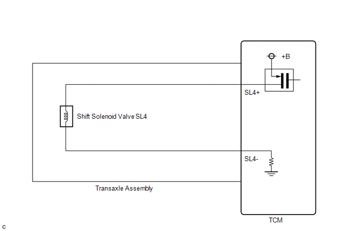
Changing from 1st to 6th is performed by the TCM turning shift solenoid valves
SL1, SL2, SL3, SL4 and SL on and off. If an open or short circuit occurs in any
of the shift solenoid valves, the TCM controls the remaining normal shift solenoid
valves to allow the vehicle to be operated (See page
.gif) )
)
|
DTC No. |
DTC Detection Condition |
Trouble Area |
|---|---|---|
|
P2810 |
The TCM checks for an open or short in the shift solenoid valve SL4 circuit while driving and shifting gears. (1-trip detection logic)
|
|
MONITOR DESCRIPTION
The TCM commands gear shifts by turning the shift solenoid valves on or off. When there is an open or short circuit in any shift solenoid valve circuit, the TCM detects the problem and illuminates the MIL and stores the DTC. And the TCM performs the fail-safe function and turns the other normal shift solenoid valves on or off (In case of an open or short circuit, the TCM stops sending current to the circuit.)
(See page ).
MONITOR STRATEGY
|
Related DTCs |
P2810: Shift solenoid valve SL4/Range check |
|
Required sensors/Components |
Shift solenoid valve SL4 |
|
Frequency of operation |
Continuous |
|
Duration |
1 sec. |
|
MIL operation |
Immediate |
|
Sequence of operation |
None |
TYPICAL ENABLING CONDITIONS
All|
The monitor will run whenever the following DTCs are not present |
None |
|
Ignition switch |
ON |
|
Starter |
OFF |
|
Battery voltage |
12 V or more |
|
Battery voltage |
10 V or more and less than 12 V |
|
Target current |
Less than 0.75 A |
|
Battery voltage |
8 V or more |
|
Target current |
0.25 A or more |
TYPICAL MALFUNCTION THRESHOLDS
Condition (A) and (B)|
Output duty cycle |
100% or more |
|
Output duty cycle |
0% or less |
COMPONENT OPERATING RANGE
|
Output duty cycle |
More than 3% and less than 100% |
WIRING DIAGRAM
CAUTION / NOTICE / HINT
NOTICE:
Perform the universal trip to clear permanent DTCs (See page
).
PROCEDURE
|
1. |
INSPECT TRANSMISSION WIRE (SL4) |
|
(a) Remove the TCM from the transaxle. |
|
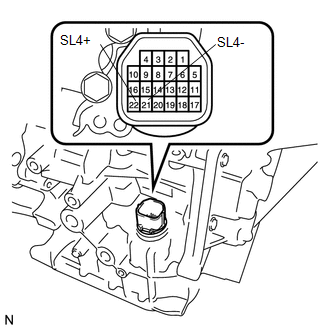
(b) Measure the resistance according to the value(s) in the table below.
Standard Resistance:
|
Tester Connection |
Condition |
Specified Condition |
|---|---|---|
|
22 (SL4+) - 21 (SL4-) |
20°C (68°F) |
5.0 to 5.6 Ω |
|
22 (SL4+) - Body ground |
Always |
10 kΩ or higher |
|
21 (SL4-) - Body ground |
Always |
10 kΩ or higher |
|
22 (SL4+) - All other terminals except 21 (SL4-) |
Always |
10 kΩ or higher |
|
21 (SL4-) - All other terminals except 22 (SL4+) |
Always |
10 kΩ or higher |
| OK | .gif) |
REPLACE TCM |
|
.gif)
|
2. |
INSPECT SHIFT SOLENOID VALVE SL4 |
|
(a) Remove shift solenoid valve SL4. |
|
.png)
(b) Measure the resistance according to the value(s) in the table below.
Standard Resistance:
|
Tester Connection |
Condition |
Specified Condition |
|---|---|---|
|
1 - 2 |
20°C (68°F) |
5.0 to 5.6 Ω |
|
*1 |
Shift Solenoid Valve SL4 |
(c) Connect a battery positive (+) lead with a 21 W bulb to terminal 2 and a negative (-) lead to terminal 1 of the solenoid valve connector. Then check that the valve moves and makes an operating sound.
OK:
Valve moves and makes an operating sound.
| OK | |
REPLACE TRANSMISSION WIRE |
| NG | |
REPLACE SHIFT SOLENOID VALVE SL4 |
 Pressure Control Solenoid "G" Performance (Shift Solenoid Valve SL4) (P2808)
DESCRIPTION
The TCM uses the vehicle speed signal and signals from the transmission speed
sensors (NC, NT) to detect the actual gear (1st, 2nd, 3rd, 4th, 5th or 6th gear).
Then the TCM compares th ...
 Lost Communication with ECM / PCM "A" (U0100)
DESCRIPTION
The engine control unit communicates with the TCM using the Controller Area Network
(CAN).
If there is a problem in this communication, the TCM sets a DTC.
DTC No.
...
Other materials about Toyota Venza:
Removal
REMOVAL
PROCEDURE
1. REMOVE NO. 1 FLOOR UNDER COVER
(a) Disengage the 4 nuts and clip, and remove the No. 1 floor under cover.
Text in Illustration
Nut (attached to under cover)
HINT:
Rotate the clip to disengage it. The 4 ...
Diagnostic Trouble Code Chart
DIAGNOSTIC TROUBLE CODE CHART
HINT:
If a trouble code is stored during the DTC check, inspect the trouble areas listed
for that code. For details of the code, refer to "See page" below.
1. TRANSPONDER KEY ECU DIAGNOSTIC TROUBLE CODE CHART
Trans ...
Blower Motor Circuit
DESCRIPTION
The blower motor is operated by signals from the A/C amplifier. Blower motor
speed signals are transmitted in accordance with changes in the duty ratio.
WIRING DIAGRAM
CAUTION / NOTICE / HINT
NOTICE:
Inspect the fuses for circuits related ...

0.1343