Toyota Venza: Pressure Control Solenoid "D" Electrical (Shift Solenoid Valve SLT) (P2716)
DESCRIPTION
Refer to DTC P2714 (See page .gif) ).
).
|
DTC No. |
DTC Detection Condition |
Trouble Area |
|---|---|---|
|
P2716 |
Open or short is detected in shift solenoid valve SLT circuit for 1 second or more while driving (1-trip detection logic). |
|
MONITOR DESCRIPTION
When an open or short in the linear solenoid valve (SLT) circuit is detected, the TCM interprets this as a fault. The TCM will turn on the MIL and store the DTC.
MONITOR STRATEGY
|
Related DTCs |
P2716: Shift solenoid valve SLT/Range check |
|
Required sensors/Components |
Shift solenoid valve SLT |
|
Frequency of operation |
Continuous |
|
Duration |
1 sec. |
|
MIL operation |
Immediate |
|
Sequence of operation |
None |
TYPICAL ENABLING CONDITIONS
ALL:|
The monitor will run whenever this DTC is not present |
None |
|
Solenoid current cut status |
Not cut |
|
Ignition switch |
ON |
|
Starter |
OFF |
|
Battery voltage |
12 V or more |
|
Target current |
1 A |
|
Battery voltage |
10 V or more and less than 12 V |
|
Target current |
Less than 0.75 A |
|
Battery voltage |
8 V or more |
|
Target current |
1 A |
|
Battery voltage |
11 V or more |
|
Target current |
1 A or more |
|
Battery voltage |
11 V or more |
|
Target current |
0.1 A or more |
|
Target voltage - Last target voltage |
Less than 0.0000191 V |
TYPICAL MALFUNCTION THRESHOLDS
Malfunction (A) and (B):|
Output duty cycle |
100% or more |
|
Output duty cycle |
0% or less |
|
Solenoid voltage monitor |
No signal |
|
Target voltage - Average of monitor voltage |
0.035 V or more |
COMPONENT OPERATING RANGE
|
Output duty cycle |
Less than 100% |
WIRING DIAGRAM
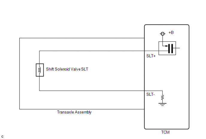
CAUTION / NOTICE / HINT
NOTICE:
Perform the universal trip to clear permanent DTCs (See page
).
PROCEDURE
|
1. |
INSPECT TRANSMISSION WIRE (SLT) |
|
(a) Remove the TCM from the transaxle. |
|
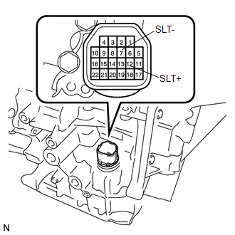
(b) Measure the resistance according to the value(s) in the table below.
Standard Resistance:
|
Tester Connection |
Condition |
Specified Condition |
|---|---|---|
|
12 (SLT+) - 7 (SLT-) |
20°C (68°F) |
5.0 to 5.6 Ω |
|
12 (SLT+) - Body ground |
Always |
10 kΩ or higher |
|
7 (SLT-) - Body ground |
Always |
10 kΩ or higher |
|
12 (SLT+) - All other terminals except 7 (SLT-) |
Always |
10 kΩ or higher |
|
7 (SLT-) - All other terminals except 12 (SLT+) |
Always |
10 kΩ or higher |
| OK | .gif) |
REPLACE TCM |
|
.gif)
|
2. |
INSPECT SHIFT SOLENOID VALVE SLT |
|
(a) Remove shift solenoid valve SLT. |
|
.png)
(b) Measure the resistance according to the value(s) in the table below.
Standard Resistance:
|
Tester Connection |
Condition |
Specified Condition |
|---|---|---|
|
1 - 2 |
20°C (68°F) |
5.0 to 5.6 Ω |
|
*1 |
Shift Solenoid Valve SLT |
(c) Connect a battery positive (+) lead with a 21 W bulb to terminal 2 and a negative (-) lead to terminal 1 of the solenoid valve connector. Then check that the valve moves and makes an operating sound.
OK:
Valve moves and makes an operating sound.
| OK | |
REPLACE TRANSMISSION WIRE |
| NG | |
REPLACE SHIFT SOLENOID VALVE SLT |
 Torque Converter Clutch Pressure Control Solenoid Control Circuit Electrical
(Shift Solenoid Valve SLU) (P2759)
Torque Converter Clutch Pressure Control Solenoid Control Circuit Electrical
(Shift Solenoid Valve SLU) (P2759)
DESCRIPTION
The amount of current flow to the solenoid is controlled by the duty ratio of
the TCM output signal. The higher the duty ratio becomes, the higher the lock-up
hydraulic pressure becom ...
 Torque Converter Clutch Pressure Control Solenoid Performance (Shift Solenoid
Valve SLU) (P2757)
Torque Converter Clutch Pressure Control Solenoid Performance (Shift Solenoid
Valve SLU) (P2757)
SYSTEM DESCRIPTION
The TCM uses the signals from the throttle position sensor, air-flow meter, turbine
(input) speed sensor, output speed sensor and crankshaft position sensor to monitor
the enga ...
Other materials about Toyota Venza:
Installation
INSTALLATION
PROCEDURE
1. INSTALL FRONT SUSPENSION MEMBER BODY MOUNTING REAR CUSHION LH
(a) Temporarily install a new front suspension member body mounting rear
cushion LH while confirming the installation direction.
NOTICE:
Position th ...
System Description
SYSTEM DESCRIPTION
1. FRONT POWER SEAT CONTROL SYSTEM DESCRIPTION
The driver seat is equipped with slide, reclining, lifter, front vertical and
lumbar support adjustment functions.
2. FUNCTION OF MAIN COMPONENTS
The following functions are available:
...
Yaw Rate Sensor Output Malfunction (C1448/98)
DESCRIPTION
The skid control ECU receives signals from the yaw rate and acceleration sensor
via the CAN communication system.
The yaw rate sensor has a built-in acceleration sensor and detects the vehicle
condition.
DTC Code
DTC De ...

0.1751