Toyota Venza: Pressure Control Solenoid "C" Electrical (Shift Solenoid Valve SL3) (P0798)
DESCRIPTION
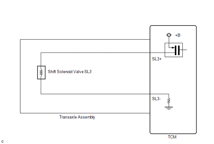
Changing from 1st to 6th is performed by the TCM turning shift solenoid valves
SL1, SL2, SL3, SL4 and SL on and off. If an open or short circuit occurs in any
of the shift solenoid valves, the TCM controls the remaining normal shift solenoid
valves to allow the vehicle to be operated (See page
.gif) ).
).
|
DTC No. |
DTC Detection Condition |
Trouble Area |
|---|---|---|
|
P0798 |
The TCM checks for an open or short in the shift solenoid valve SL3 circuit while driving and shifting gears. (1-trip detection logic)
|
|
MONITOR DESCRIPTION
The TCM commands gear shifts by turning the shift solenoid valves on or off. When there is an open or short circuit in any shift solenoid valve circuit, the TCM detects the problem and illuminates the MIL and stores the DTC. And the TCM performs the fail-safe function and turns the other normal shift solenoid valves on or off (In case of an open or short circuit, the TCM stops sending current to the circuit.)
(See page ).
MONITOR STRATEGY
|
Related DTCs |
P0798: Shift solenoid valve SL3/Range check |
|
Required sensors/Components |
Shift solenoid valve SL3 |
|
Frequency of operation |
Continuous |
|
Duration |
1 sec. |
|
MIL operation |
Immediate |
|
Sequence of operation |
None |
TYPICAL ENABLING CONDITIONS
All|
The monitor will run whenever the following DTCs are not present |
None |
|
Ignition switch |
ON |
|
Starter |
OFF |
|
Battery voltage |
12 V or more |
|
Battery voltage |
10 V or more and less than 12 V |
|
Target current |
Less than 0.75 A |
|
Battery voltage |
8 V or more |
|
Target current |
0.25 A or more |
TYPICAL MALFUNCTION THRESHOLDS
Condition (A) and (B)|
Output duty cycle |
100% or more |
|
Output duty cycle |
0% or less |
COMPONENT OPERATING RANGE
|
Output duty cycle |
More than 3% and less than 100% |
WIRING DIAGRAM
CAUTION / NOTICE / HINT
NOTICE:
Perform the universal trip to clear permanent DTCs (See page
).
PROCEDURE
|
1. |
INSPECT TRANSMISSION WIRE (SL3) |
|
(a) Remove the TCM from the transaxle. |
|
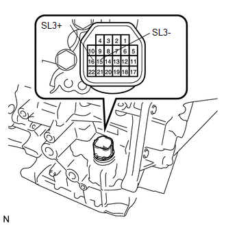
(b) Measure the resistance according to the value(s) in the table below.
Standard Resistance:
|
Tester Connection |
Condition |
Specified Condition |
|---|---|---|
|
16 (SL3+) - 15 (SL3-) |
20°C (68°F) |
5.0 to 5.6 Ω |
|
16 (SL3+) - Body ground |
Always |
10 kΩ or higher |
|
15 (SL3-) - Body ground |
Always |
10 kΩ or higher |
|
16 (SL3+) - All other terminals except 15 (SL3-) |
Always |
10 kΩ or higher |
|
15 (SL3-) - All other terminals except 16 (SL3+) |
Always |
10 kΩ or higher |
| OK | .gif) |
REPLACE TCM |
|
.gif)
|
2. |
INSPECT SHIFT SOLENOID VALVE SL3 |
|
(a) Remove shift solenoid valve SL3. |
|
.png)
(b) Measure the resistance according to the value(s) in the table below.
Standard Resistance:
|
Tester Connection |
Condition |
Specified Condition |
|---|---|---|
|
1 - 2 |
20°C (68°F) |
5.0 to 5.6 Ω |
|
*1 |
Shift Solenoid Valve SL3 |
(c) Connect a battery positive (+) lead with a 21 W bulb to terminal 2 and a negative (-) lead to terminal 1 of the solenoid valve connector. Then check that the valve moves and makes an operating sound.
OK:
Valve moves and makes an operating sound.
| OK | |
REPLACE TRANSMISSION WIRE |
| NG | |
REPLACE SHIFT SOLENOID VALVE SL3 |
 Pressure Control Solenoid "D" Performance (Shift Solenoid Valve SLT) (P2714)
SYSTEM DESCRIPTION
The linear solenoid valve (SLT) controls the transmission line pressure for smooth
transmission operation based on signals from the throttle position sensor and the
vehicle spe ...
 Transmission Fluid Pressure Sensor / Switch "E" Circuit Low (P0989,P0990)
DESCRIPTION
ATF pressure switch No. 3 is installed in the lock-up solenoid ATF output passage
and is used to detect a malfunction in the lock-up solenoid.
DTC No.
DTC Detecti ...
Other materials about Toyota Venza:
Power Seat does not Return to Memorized Position
DESCRIPTION
When either the M1 or M2 switch is pressed, the outer mirror control ECU assembly
LH sends a switch signal to the main body ECU (driver side junction block assembly)
via CAN communication. Then, the main body ECU (driver side junction block as ...
Terminals Of Ecu
TERMINALS OF ECU
1. CHECK AIR CONDITIONING AMPLIFIER ASSEMBLY
(a) Disconnect the D47 air conditioning amplifier assembly connector.
(b) Measure the voltage and resistance according to the value(s) in the table
below.
HINT:
Measure the values on the wi ...
Taillight Relay Circuit
DESCRIPTION
The main body ECU (driver side junction block assembly) controls the operation
of the TAIL relay.
WIRING DIAGRAM
CAUTION / NOTICE / HINT
NOTICE:
Inspect the fuses for circuits related to this system before performing the following
inspec ...

0.177