Toyota Venza: IG2 Signal Malfunction (B2788)
DESCRIPTION
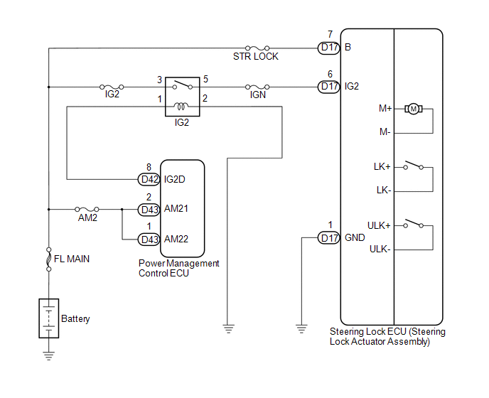
The steering lock ECU (steering lock actuator assembly) receives power from the IG2 relay. When the voltage value indicated by the IG signal from the certification ECU (smart key ECU assembly) equals to the voltage that is applied to the steering lock ECU (steering lock actuator assembly), the steering wheel will be unlocked. The steering lock ECU (steering lock actuator assembly) will not lock the steering wheel when power from the IG2 relay is present. This prevents the steering from being locked while the vehicle is moving.
|
DTC No. |
DTC Detecting Condition |
Trouble Area |
|---|---|---|
|
B2788 |
Different information is obtained from IG2 signals received directly from the IG2 circuit, and from IG2 signals sent via LIN communication for 1 second. |
|
WIRING DIAGRAM
CAUTION / NOTICE / HINT
HINT:
After replacing the steering lock ECU (steering lock actuator assembly), confirm
the Initialization of the steering lock (See page
.gif) ).
).
PROCEDURE
|
1. |
INSPECT NO. 2 IGNITION RELAY |
|
(a) Remove the IG2 relay from the engine room junction block and relay block. |
|
(b) Measure the resistance according to the value(s) in the table below.
Standard Resistance:
|
Tester Connection |
Specified Condition |
|---|---|
|
3 - 5 |
10 kΩ or higher |
|
3 - 5 |
Below 1 Ω (when battery voltage is applied between terminals 1 and 2) |
|
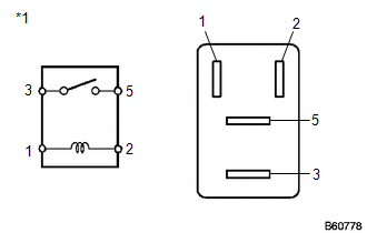
*1 |
IG2 Relay |
| NG | .gif) |
REPLACE NO. 2 IGNITION RELAY |
|
.gif)
|
2. |
CHECK HARNESS AND CONNECTOR (STEERING LOCK ECU - BODY GROUND) |
|
(a) Disconnect the D17 connector from the steering lock ECU (steering lock actuator assembly). |
|
(b) Measure the resistance according to the value(s) in the table below.
Standard Resistance:
|
Tester Connection |
Condition |
Specified Condition |
|---|---|---|
|
D17-1 (GND) - Body ground |
Always |
Below 1 Ω |
|
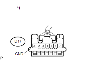
*1 |
Front view of wire harness connector (to Steering Lock ECU (Steering Lock Actuator Assembly)) |
| NG | |
REPAIR OR REPLACE HARNESS OR CONNECTOR |
|
|
3. |
CHECK HARNESS AND CONNECTOR (STEERING LOCK ECU - BATTERY) |
|
(a) Measure the voltage according to the value(s) in the table below. Standard Voltage:
|
|
(b) Measure the resistance according to the value(s) in the table below.
Standard Resistance:
|
Tester Connection |
Switch Condition |
Specified Condition |
|---|---|---|
|
*D17-6 (IG2) - D17-7 (B) |
Engine switch off |
10 kΩ or higher |
*: This measurement is performed with the engine switch off to check for a battery voltage short in the IG2 circuit.
Text in Illustration|
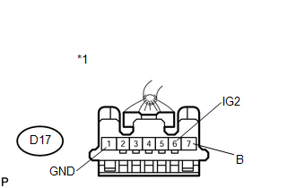
*1 |
Front view of wire harness connector (to Steering Lock ECU (Steering Lock Actuator Assembly)) |
| OK | |
REPLACE STEERING LOCK ECU (STEERING LOCK ACTUATOR ASSEMBLY) |
| NG | |
REPAIR OR REPLACE HARNESS OR CONNECTOR |
 Data List / Active Test
DATA LIST / ACTIVE TEST
1. DATA LIST
HINT:
Using the Techstream to read the Data List allows the values or states of switches,
sensors, actuators and other items to be read without removing any p ...
 Diagnostic Trouble Code Chart
DIAGNOSTIC TROUBLE CODE CHART
If a trouble code is displayed during the DTC check, check the parts listed for
that code in the table below and proceed to the appropriate page.
HINT:
The steering ...
Other materials about Toyota Venza:
Removal
REMOVAL
PROCEDURE
1. PRECAUTION
NOTICE:
After turning the ignition switch off, waiting time may be required before disconnecting
the cable from the negative (-) battery terminal. Therefore, make sure to read the
disconnecting the cable from the negativ ...
Multi-information display (LCD type)
The multi-information display presents the driver with a variety of driving-related
data, including the clock and current outside temperature.
• Clock
Indicates and sets the time.
• Outside temperature
Indicates the outside temperature.
The temper ...
Atf Temperature Sensor(when Using The Engine Support Bridge)
Components
COMPONENTS
ILLUSTRATION
Inspection
INSPECTION
PROCEDURE
1. INSPECT ATF TEMPERATURE SENSOR ASSEMBLY
(a) Measure the resistance according to the value(s) in the table below.
Standard Resistance:
Tester C ...

0.1645