Toyota Venza: Pressure Control Solenoid "B" Electrical (Shift Solenoid Valve SL2) (P0778)
DESCRIPTION
Changing from 1st to 6th is performed by the TCM turning shift solenoid valves
SL1, SL2, SL3, SL4 and SL on and off. If an open or short circuit occurs in any
of the shift solenoid valves, the TCM controls the remaining normal shift solenoid
valves to allow the vehicle to be operated (See page
.gif) ).
).
|
DTC No. |
DTC Detection Condition |
Trouble Area |
|---|---|---|
|
P0778 |
The TCM checks for an open or short in the shift solenoid valve SL2 circuit while driving and shifting gears. (1-trip detection logic)
|
|
MONITOR DESCRIPTION
This DTC indicates an open or short in the shift solenoid valve SL2 circuit. The TCM commands gear shifts by turning the shift solenoid valves on or off. When there is an open or short circuit in any of the shift solenoid valve circuits, the TCM detects the problem and illuminates the MIL and stores the DTC. The TCM also performs the fail-safe function and turns the other normal shift solenoid valves on or off. (In case of an open or short circuit, the TCM stops sending current to the circuit.)
While driving and shifting gears, if the TCM detects an open or short in the
shift solenoid valve SL2 circuit, the TCM determines there is a malfunction (See
page ).
MONITOR STRATEGY
|
Related DTCs |
P0778: Shift solenoid valve SL2/Range check |
|
Required sensors/Components |
Shift solenoid valve SL2 |
|
Frequency of operation |
Continuous |
|
Duration |
1 sec. |
|
MIL operation |
Immediate |
|
Sequence of operation |
None |
TYPICAL ENABLING CONDITIONS
All|
The monitor will run whenever the following DTCs are not present |
None |
|
Ignition switch |
ON |
|
Starter |
OFF |
|
Battery voltage |
12 V or more |
|
Battery voltage |
10 V or more and less than 12 V |
|
Target current |
Less than 0.75 A |
|
Battery voltage |
8 V or more |
|
Target current |
0.25 A or more |
TYPICAL MALFUNCTION THRESHOLDS
Condition (A) and (B)|
Output duty cycle |
100% or more |
|
Output duty cycle |
0% or less |
COMPONENT OPERATING RANGE
|
Output duty cycle |
More than 3% and less than 100% |
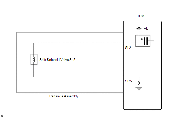
WIRING DIAGRAM
CAUTION / NOTICE / HINT
NOTICE:
Perform the universal trip to clear permanent DTCs (See page
).
HINT:
The following table shows normal operation of the shift solenoid valve SL2 when the shift lever is in D:
|
TCM commanded gear |
1st |
2nd |
3rd |
4th |
5th |
6th |
|
Shift solenoid valve SL2 |
OFF |
OFF |
OFF |
ON |
ON |
ON |
PROCEDURE
|
1. |
INSPECT TRANSMISSION WIRE (SL2) |
|
(a) Remove the TCM from the transaxle. |
|
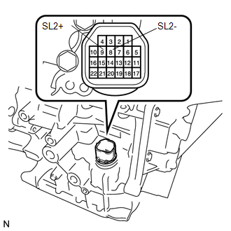
(b) Measure the resistance according to the value(s) in the table below.
Standard Resistance:
|
Tester Connection |
Condition |
Specified Condition |
|---|---|---|
|
9 (SL2+) - 8 (SL2-) |
20°C (68°F) |
5.0 to 5.6 Ω |
|
9 (SL2+) - Body ground |
Always |
10 kΩ or higher |
|
8 (SL2-) - Body ground |
Always |
10 kΩ or higher |
|
9 (SL2+) - All other terminals except 8 (SL2-) |
Always |
10 kΩ or higher |
|
8 (SL2-) - All other terminals except 9 (SL2+) |
Always |
10 kΩ or higher |
| OK | .gif) |
REPLACE TCM |
|
.gif)
|
2. |
INSPECT SHIFT SOLENOID VALVE SL2 |
|
(a) Remove shift solenoid valve SL2. |
|
.png)
(b) Measure the resistance according to the value(s) in the table below.
Standard Resistance:
|
Tester Connection |
Condition |
Specified Condition |
|---|---|---|
|
1 - 2 |
20°C (68°F) |
5.0 to 5.6 Ω |
|
*1 |
Shift Solenoid Valve SL2 |
(c) Connect a battery positive (+) lead with a 21 W bulb to terminal 2 and a negative (-) lead to terminal 1 of the solenoid valve connector. Then check that the valve moves and makes an operating sound.
OK:
Valve moves and makes an operating sound.
| OK | |
REPAIR OR REPLACE TRANSMISSION WIRE |
| NG | |
REPLACE SHIFT SOLENOID VALVE SL2 |
 Pressure Control Solenoid "B" Performance (Shift Solenoid Valve SL2) (P0776)
SYSTEM DESCRIPTION
The TCM uses the vehicle speed signal and signals from the transmission speed
sensors (NC, NT) to detect the actual gear (1st, 2nd, 3rd, 4th, 5th or 6th gear).
Then the TCM comp ...
 Pressure Control Solenoid "A" Electrical (Shift Solenoid Valve SL1) (P0748)
DESCRIPTION
Changing from 1st to 6th is performed by the TCM turning shift solenoid valves
SL1, SL2, SL3, SL4 and SL on and off. If an open or short circuit occurs in any
of the shift solenoid va ...
Other materials about Toyota Venza:
System Description
SYSTEM DESCRIPTION
1. FRONT POWER SEAT CONTROL SYSTEM DESCRIPTION
The driver seat is equipped with slide, reclining, lifter, front vertical,
and lumbar support adjustment functions.
The memory call function uses the key ID code of the key to m ...
Problem Symptoms Table
PROBLEM SYMPTOMS TABLE
HINT:
Use the table below to help determine the cause of problem symptoms. If multiple
suspected areas are listed, the potential causes of the symptoms are listed in order
of probability in the "Suspected Area" column of ...
Trailer towing
Your vehicle is designed primarily as a passenger-and-load-carrying vehicle.
Towing a trailer can have an adverse impact on handling, performance, braking, durability,
and fuel consumption. For your safety and the safety of others, you must not overload
...

0.1572