Toyota Venza: Terminals Of Ecu
TERMINALS OF ECU
NOTICE:
- Turn the ignition switch off before measuring the resistances between CAN bus main wires and between CAN bus branch wires.
- Turn the ignition switch off before inspecting CAN bus wires for a ground short.
- After the ignition switch is turned off, check that the key reminder warning system and light reminder warning system are not operating.
- Before measuring the resistance, leave the vehicle as is for at least 1 minute and do not operate the ignition switch, any other switches or the doors. If any doors need to be opened in order to check connectors, open the doors and leave them open.
HINT:
- Operating the ignition switch, any other switches or a door triggers related ECU and sensor communication on the CAN. This communication will cause the resistance value to change.
- Even after DTCs are cleared, if a DTC is stored again after driving the vehicle for a while, the malfunction may be occurring due to vibration of the vehicle. In such a case, wiggling the ECUs or wire harness while performing the inspection below may help determine the cause of the malfunction.
NOTICE:
This section describes the standard CAN values for all CAN related components.
1. CAN NO. 1 JUNCTION CONNECTOR
 Text in Illustration
|
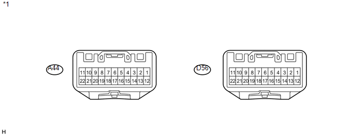
*1 |
Component without harness connected (CAN No. 1 Junction Connector) |
(a) Check the CAN No. 1 junction connector (A44).
 Text in Illustration
|
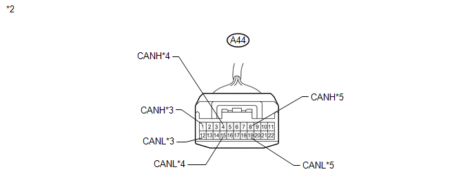
*2 |
Front view of wire harness connector (to CAN No. 1 Junction Connector) |
|
*3 |
to Skid Control ECU |
|
*4 |
to ECM (CAN No. 1 Bus) |
|
*5 |
to ECM (Power Management Bus)*1 |
*1: w/ Smart key system
(b) Check the connection diagram of the components which are connected to the
CAN No. 1 junction connector (See page .gif) ).
).
|
Terminal No. (Symbol) |
Wiring Color |
Connected to |
|---|---|---|
|
A44-1 (CANH) |
GR |
Skid control ECU |
|
A44-12 (CANL) |
W |
|
|
A44-4 (CANH) |
Y |
ECM (CAN No. 1 bus) |
|
A44-15 (CANL) |
W |
|
|
A44-8 (CANH) |
G |
ECM*1 (Power management bus) |
|
A44-19 (CANL) |
W |
*1: w/ Smart key system
(c) Check the CAN No. 1 junction connector (D56).
 Text in Illustration
|
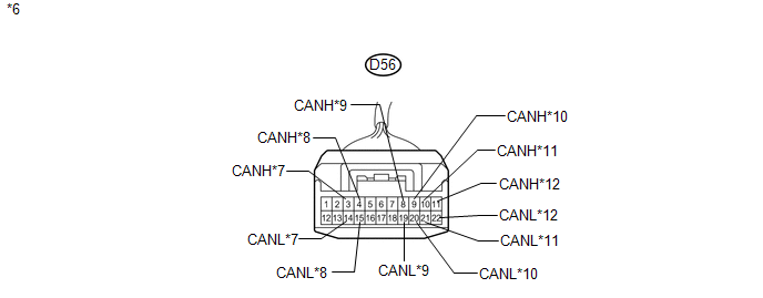
*6 |
Front view of wire harness connector (to CAN No. 1 Junction Connector) |
|
*7 |
to Air Conditioning Amplifier (Power Management Bus)*1 |
|
*8 |
to Power Management Control ECU (Power Management Bus)*1 |
|
*9 |
to Air Conditioning Amplifier (CAN No. 1 Bus)*2 |
|
*10 |
to CAN No. 2 Junction Connector |
|
*11 |
to Power Management Control ECU (CAN No. 1 Bus)*1 |
|
*12 |
to 4WD Control ECU*3 |
*1: w/ Smart key system
*2: w/o Smart key system
*3: for AWD
(d) Check the connection diagram of the components which are connected to the
CAN No. 1 junction connector (See page ).
|
Terminal No. (Symbol) |
Wiring Color |
Connected to |
|---|---|---|
|
D56-3 (CANH) |
P |
Air conditioning amplifier*1 (Power management bus) |
|
D56-14 (CANL) |
W |
|
|
D56-4 (CANH) |
G |
Power management control ECU*1 (Power management bus) |
|
D56-15 (CANL) |
W |
|
|
D56-8 (CANH) |
P |
Air conditioning amplifier*2 (CAN No. 1 bus) |
|
D56-19 (CANL) |
W |
|
|
D56-9 (CANH) |
R |
CAN No. 2 junction connector |
|
D56-20 (CANL) |
W |
|
|
D56-10 (CANH) |
Y |
Power management control ECU*1 (CAN No. 1 bus) |
|
D56-21 (CANL) |
W |
|
|
D56-11 (CANH) |
L |
4WD control ECU*3 |
|
D56-22 (CANL) |
W |
*1: w/ Smart key system
*2: w/o Smart key system
*3: for AWD
2. CAN NO. 2 JUNCTION CONNECTOR
(a) Check the CAN No. 2 junction connector.
 Text in Illustration
|
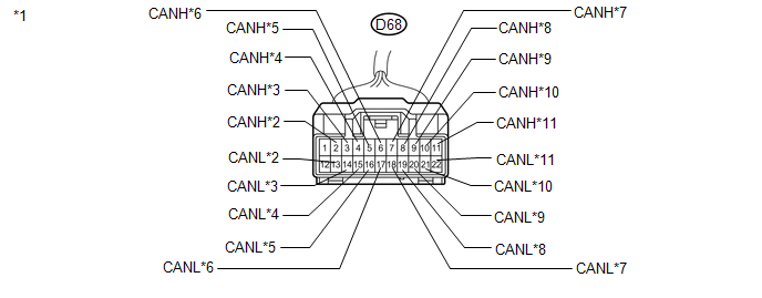
*1 |
Front view of wire harness connector (to CAN No. 2 Junction Connector) |
|
*2 |
to Center Airbag Sensor Assembly |
|
*3 |
to Yaw Rate Sensor |
|
*4 |
to Main Body ECU |
|
*5 |
to Steering Angle Sensor |
|
*6 |
to DLC3 |
|
*7 |
to Power Steering ECU |
|
*8 |
to Combination Meter |
|
*9 |
to CAN No. 1 Junction Connector |
|
*10 |
to Certification ECU |
|
*11 |
|
*1: for Navigation system
*2: for Audio and visual system
(b) Check the connection diagram of the components which are connected to the
CAN No. 2 junction connector (See page ).
|
Terminal No. (Symbol) |
Wiring Color |
Connected to |
|---|---|---|
|
D68-2 (CANH) |
SB |
Center airbag sensor assembly |
|
D68-13 (CANL) |
W |
|
|
D68-3 (CANH) |
V |
Yaw rate sensor |
|
D68-14 (CANL) |
W |
|
|
D68-4 (CANH) |
P |
Main body ECU |
|
D68-15 (CANL) |
W |
|
|
D68-5 (CANH) |
L |
Steering angle sensor |
|
D68-16 (CANL) |
W |
|
|
D68-6 (CANH) |
Y |
DLC3 |
|
D68-17 (CANL) |
W |
|
|
D68-7 (CANH) |
BR |
Power steering ECU |
|
D68-18 (CANL) |
W |
|
|
D68-8 (CANH) |
LG |
Combination meter |
|
D68-19 (CANL) |
W |
|
|
D68-9 (CANH) |
R |
CAN No. 1 junction connector |
|
D68-20 (CANL) |
W |
|
|
D68-10 (CANH) |
G |
Certification ECU |
|
D68-21 (CANL) |
W |
|
|
D68-11 (CANH) |
SB |
|
|
D68-22 (CANL) |
W |
*1: for Navigation system
*2: for Audio and visual system
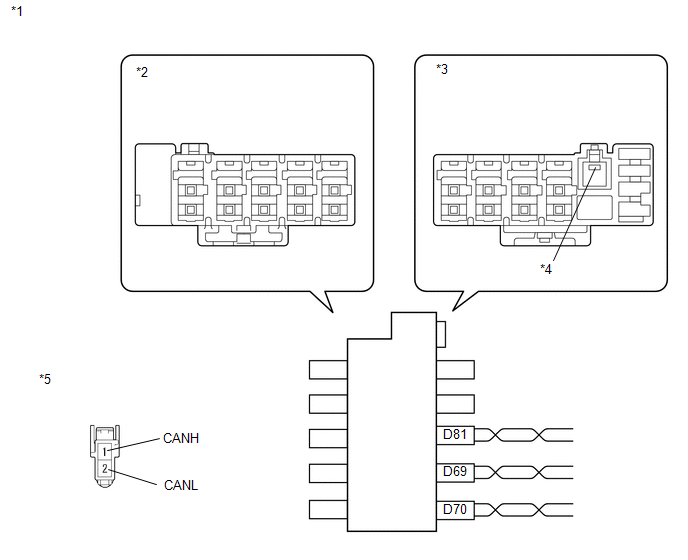
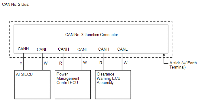
3. CAN NO. 3 JUNCTION CONNECTOR
 Text in Illustration
|
*1 |
CAN No. 3 Junction Connector |
|
*2 |
Junction Connector B Side |
|
*3 |
Junction Connector A Side |
|
*4 |
Earth Terminal |
|
*5 |
Front view of wire harness connector (to CAN No. 3 Junction Connector) |
(a) Check the connection diagram of the components which are connected to the CAN No. 3 junction connector.
 for CAN No. 3 Junction Connector
A Side
|
Terminal No. (Symbol) |
Wiring Color |
Connected to |
|---|---|---|
|
D69-1 (CANH) |
R |
Power management control ECU*1 (CAN No. 2 bus) |
|
D69-2 (CANL) |
W |
|
|
D70-1 (CANH) |
Y |
AFS ECU*2 |
|
D70-2 (CANL) |
W |
|
|
D81-1 (CANH) |
R |
Clearance warning ECU assembly*3 |
|
D81-2 (CANL) |
W |
*1: w/ Smart key system
*2: w/ HID headlight
*3: w/ Intuitive parking assist system
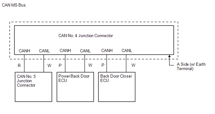
4. CAN NO. 4 JUNCTION CONNECTOR
 Text in Illustration
|
*1 |
CAN No. 4 Junction Connector |
|
*2 |
Junction Connector B Side |
|
*3 |
Junction Connector A Side |
|
*4 |
Earth Terminal |
|
*5 |
Front view of wire harness connector (to CAN No. 4 Junction Connector) |
(a) Check the connection diagram of the components which are connected to the CAN No. 4 junction connector.
 for CAN No. 4 Junction Connector
A Side
|
Terminal No. (Symbol) |
Wiring Color |
Connected to |
|---|---|---|
|
L27-1 (CANH) |
R |
CAN No. 5 junction connector |
|
L27-2 (CANL) |
W |
|
|
L28-1 (CANH) |
P |
Power back door ECU*1 |
|
L28-2 (CANL) |
W |
|
|
L29-1 (CANH) |
P |
Back door closer ECU*2 |
|
L29-2 (CANL) |
W |
*1: w/ Power back door system
*2: w/ Back door closer system
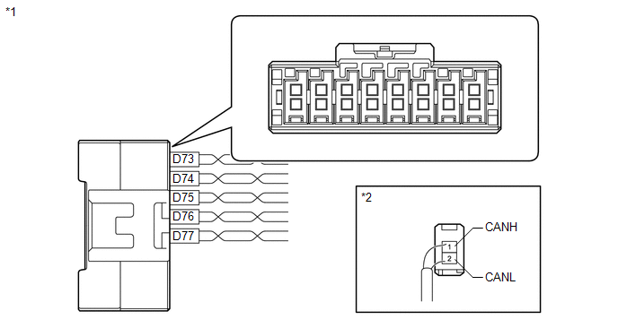
5. CAN NO. 5 JUNCTION CONNECTOR
 Text in Illustration
|
*1 |
CAN No. 5 Junction Connector |
|
*2 |
Rear view of wire harness connector (to CAN No. 5 Junction Connector) |
|
Terminal No. (Symbol) |
Wiring Color |
Connected to |
|---|---|---|
|
D73-1 (CANH) |
SB |
Main body ECU |
|
D73-2 (CANL) |
W |
|
|
D74-1 (CANH) |
P |
Outer mirror control ECU assembly*1 (for Front passenger side) |
|
D74-2 (CANL) |
W |
|
|
D75-1 (CANH) |
L |
Outer mirror control ECU assembly*1 (for Driver side) |
|
D75-2 (CANL) |
W |
|
|
D76-1 (CANH) |
G |
Position control ECU and switch assembly*1 |
|
D76-2 (CANL) |
R |
|
|
D77-1 (CANH) |
R |
CAN No. 4 junction connector |
|
D77-2 (CANL) |
W |
*1: w/ Seat position memory system
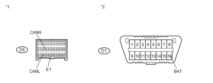
6. DLC3
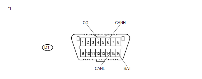 Text in Illustration
|
*1 |
DLC3 |
(a) Measure the resistance according to the value(s) in the table below.
Standard Resistance:
|
Terminal No. (Symbol) |
Wiring Color |
Terminal Description |
Condition |
Specified Condition |
|---|---|---|---|---|
|
D1-6 (CANH) - D1-14 (CANL) |
Y - W |
HIGH-level CAN bus line - LOW-level CAN bus line |
Ignition switch off |
54 to 69 Ω |
|
D1-6 (CANH) - D1-16 (BAT) |
Y - LG |
HIGH-level CAN bus line - Battery positive (+) |
Cable disconnected from negative (-) battery terminal |
6 kΩ or higher |
|
D1-14 (CANL) - D1-16 (BAT) |
W - LG |
LOW-level CAN bus line - Battery positive (+) |
Cable disconnected from negative (-) battery terminal |
6 kΩ or higher |
|
D1-6 (CANH) - D1-4 (CG) |
Y - B |
HIGH-level CAN bus line - Ground |
Ignition switch off |
200 Ω or higher |
|
D1-14 (CANL) - D1-4 (CG) |
W - B |
LOW-level CAN bus line - Ground |
Ignition switch off |
200 Ω or higher |
7. ECM (for 1AR-FE)
(a) Disconnect the connectors of the ECM.
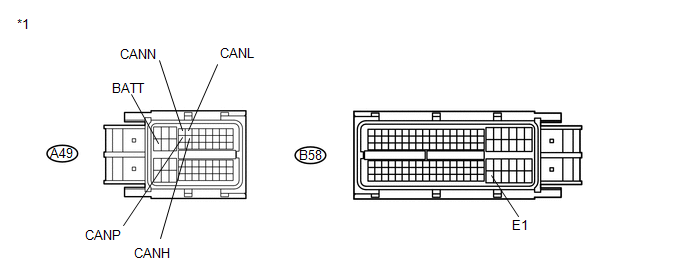 Text in Illustration
|
*1 |
Front view of wire harness connector (to ECM) |
(b) Measure the resistance according to the value(s) in the table below.
Standard Resistance:
for CAN No. 1 Bus Main Wire|
Terminal No. (Symbol) |
Wiring Color |
Terminal Description |
Condition |
Specified Condition |
|---|---|---|---|---|
|
A49-13 (CANH) - A49-5 (CANL) |
Y - W |
HIGH-level CAN bus line - LOW-level CAN bus line |
Ignition switch off |
108 to 132 Ω |
|
A49-13 (CANH) - A49-20 (BATT) |
Y - V |
HIGH-level CAN bus line - Battery positive (+) |
Cable disconnected from negative (-) battery terminal |
6 kΩ or higher |
|
A49-5 (CANL) - A49-20 (BATT) |
W - V |
LOW-level CAN bus line - Battery positive (+) |
Cable disconnected from negative (-) battery terminal |
6 kΩ or higher |
|
A49-13 (CANH) - B58-104 (E1) |
Y - BR |
HIGH-level CAN bus line - Ground |
Ignition switch off |
200 Ω or higher |
|
A49-5 (CANL) - B58-104 (E1) |
W - BR |
LOW-level CAN bus line - Ground |
Ignition switch off |
200 Ω or higher |
|
Terminal No. (Symbol) |
Wiring Color |
Terminal Description |
Condition |
Specified Condition |
|---|---|---|---|---|
|
A49-12 (CANP) - A49-4 (CANN) |
G - W |
HIGH-level CAN bus line - LOW-level CAN bus line |
Ignition switch off |
108 to 132 Ω |
|
A49-12 (CANP) - A49-20 (BATT) |
G - V |
HIGH-level CAN bus line - Battery positive (+) |
Cable disconnected from negative (-) battery terminal |
6 kΩ or higher |
|
A49-4 (CANN) - A49-20 (BATT) |
W - V |
LOW-level CAN bus line - Battery positive (+) |
Cable disconnected from negative (-) battery terminal |
6 kΩ or higher |
|
A49-12 (CANP) - B58-104 (E1) |
G - BR |
HIGH-level CAN bus line - Ground |
Ignition switch off |
200 Ω or higher |
|
A49-4 (CANN) - B58-104 (E1) |
W - BR |
LOW-level CAN bus line - Ground |
Ignition switch off |
200 Ω or higher |
8. ECM (for 2GR-FE)
(a) Disconnect the connectors of the ECM.
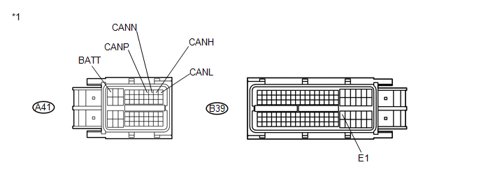 Text in Illustration
|
*1 |
Front view of wire harness connector (to ECM) |
(b) Measure the resistance according to the value(s) in the table below.
Standard Resistance:
for CAN No. 1 Bus Main Wire|
Terminal No. (Symbol) |
Wiring Color |
Terminal Description |
Condition |
Specified Condition |
|---|---|---|---|---|
|
A41-10 (CANH) - A41-11 (CANL) |
Y - W |
HIGH-level CAN bus line - LOW-level CAN bus line |
Ignition switch off |
108 to 132 Ω |
|
A41-10 (CANH) - A41-1 (BATT) |
Y - V |
HIGH-level CAN bus line - Battery positive (+) |
Cable disconnected from negative (-) battery terminal |
6 kΩ or higher |
|
A41-11 (CANL) - A41-1 (BATT) |
W - V |
LOW-level CAN bus line - Battery positive (+) |
Cable disconnected from negative (-) battery terminal |
6 kΩ or higher |
|
A41-10 (CANH) - B39-81 (E1) |
Y - W |
HIGH-level CAN bus line - Ground |
Ignition switch off |
200 Ω or higher |
|
A41-11 (CANL) - B39-81 (E1) |
W - W |
LOW-level CAN bus line - Ground |
Ignition switch off |
200 Ω or higher |
|
Terminal No. (Symbol) |
Wiring Color |
Terminal Description |
Condition |
Specified Condition |
|---|---|---|---|---|
|
A41-8 (CANP) - A41-9 (CANN) |
G - W |
HIGH-level CAN bus line - LOW-level CAN bus line |
Ignition switch off |
108 to 132 Ω |
|
A41-8 (CANP) - A41-1 (BATT) |
G - V |
HIGH-level CAN bus line - Battery positive (+) |
Cable disconnected from negative (-) battery terminal |
6 kΩ or higher |
|
A41-9 (CANN) - A41-1 (BATT) |
W - V |
LOW-level CAN bus line - Battery positive (+) |
Cable disconnected from negative (-) battery terminal |
6 kΩ or higher |
|
A41-8 (CANP) - B39-81 (E1) |
G - W |
HIGH-level CAN bus line - Ground |
Ignition switch off |
200 Ω or higher |
|
A41-9 (CANN) - B39-81 (E1) |
W - W |
LOW-level CAN bus line - Ground |
Ignition switch off |
200 Ω or higher |
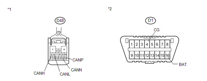
9. MAIN BODY ECU (DRIVER SIDE JUNCTION BLOCK)
(a) Disconnect the connector of the main body ECU (driver side junction block).
 Text in Illustration
|
*1 |
Front view of wire harness connector (to Main Body ECU) |
|
*2 |
DLC3 |
(b) Measure the resistance according to the value(s) in the table below.
Standard Resistance:
for CAN No. 1 Bus Branch Wire|
Terminal No. (Symbol) |
Wiring Color |
Terminal Description |
Condition |
Specified Condition |
|---|---|---|---|---|
|
D48-5 (CANH) - D48-6 (CANL) |
P - W |
HIGH-level CAN bus line - LOW-level CAN bus line |
Ignition switch off |
54 to 69 Ω |
|
D48-5 (CANH) - D1-16 (BAT) |
P - LG |
HIGH-level CAN bus line - Battery positive (+) |
Cable disconnected from negative (-) battery terminal |
6 kΩ or higher |
|
D48-6 (CANL) - D1-16 (BAT) |
W - LG |
LOW-level CAN bus line - Battery positive (+) |
Cable disconnected from negative (-) battery terminal |
6 kΩ or higher |
|
D48-5 (CANH) - D1-4 (CG) |
P - B |
HIGH-level CAN bus line - Ground |
Ignition switch off |
200 Ω or higher |
|
D48-6 (CANL) - D1-4 (CG) |
W - B |
LOW-level CAN bus line - Ground |
Ignition switch off |
200 Ω or higher |
|
Terminal No. (Symbol) |
Wiring Color |
Terminal Description |
Condition |
Specified Condition |
|---|---|---|---|---|
|
D48-16 (CANP) - D48-15 (CANN) |
SB - W |
HIGH-level CAN bus line - LOW-level CAN bus line |
Ignition switch off |
108 to 132 Ω |
|
D48-16 (CANP) - D1-16 (BAT) |
SB - LG |
HIGH-level CAN bus line - Battery positive (+) |
Cable disconnected from negative (-) battery terminal |
6 kΩ or higher |
|
D48-15 (CANN) - D1-16 (BAT) |
W - LG |
LOW-level CAN bus line - Battery positive (+) |
Cable disconnected from negative (-) battery terminal |
6 kΩ or higher |
|
D48-16 (CANP) - D1-4 (CG) |
SB - B |
HIGH-level CAN bus line - Ground |
Ignition switch off |
200 Ω or higher |
|
D48-15 (CANN) - D1-4 (CG) |
W - B |
LOW-level CAN bus line - Ground |
Ignition switch off |
200 Ω or higher |
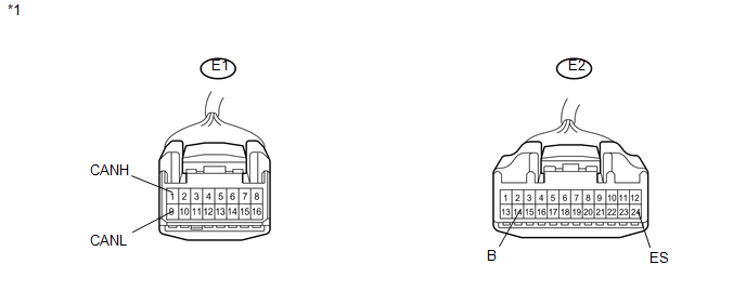
10. COMBINATION METER
(a) Disconnect the connectors of the combination meter.
 Text in Illustration
|
*1 |
Front view of wire harness connector (to Combination Meter) |
(b) Measure the resistance according to the value(s) in the table below.
Standard Resistance:
|
Terminal No. (Symbol) |
Wiring Color |
Terminal Description |
Condition |
Specified Condition |
|---|---|---|---|---|
|
E1-1 (CANH) - E1-9 (CANL) |
LG - W |
HIGH-level CAN bus line - LOW-level CAN bus line |
Ignition switch off |
108 to 132 Ω |
|
E1-1 (CANH) - E2-14 (B) |
LG - Y |
HIGH-level CAN bus line - Battery positive (+) |
Cable disconnected from negative (-) battery terminal |
6 kΩ or higher |
|
E1-9 (CANL) - E2-14 (B) |
W - Y |
LOW-level CAN bus line - Battery positive (+) |
Cable disconnected from negative (-) battery terminal |
6 kΩ or higher |
|
E1-1 (CANH) - E2-24 (ES) |
LG - W |
HIGH-level CAN bus line - Ground |
Ignition switch off |
200 Ω or higher |
|
E1-9 (CANL) - E2-24 (ES) |
W - W |
LOW-level CAN bus line - Ground |
Ignition switch off |
200 Ω or higher |
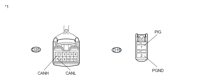
11. POWER STEERING ECU
(a) Disconnect the connectors of the power steering ECU.
 Text in Illustration
|
*1 |
Front view of wire harness connector (to Power Steering ECU) |
(b) Measure the resistance according to the value(s) in the table below.
Standard Resistance:
|
Terminal No. (Symbol) |
Wiring Color |
Terminal Description |
Condition |
Specified Condition |
|---|---|---|---|---|
|
D20-1 (CANH) - D20-7 (CANL) |
BR - W |
HIGH-level CAN bus line - LOW-level CAN bus line |
Ignition switch off |
54 to 69 Ω |
|
D20-1 (CANH) - D19-1 (PIG) |
BR - R |
HIGH-level CAN bus line - Battery positive (+) |
Cable disconnected from negative (-) battery terminal |
6 kΩ or higher |
|
D20-7 (CANL) - D19-1 (PIG) |
W - R |
LOW-level CAN bus line - Battery positive (+) |
Cable disconnected from negative (-) battery terminal |
6 kΩ or higher |
|
D20-1 (CANH) - D19-2 (PGND) |
BR - B |
HIGH-level CAN bus line - Ground |
Ignition switch off |
200 Ω or higher |
|
D20-7 (CANL) - D19-2 (PGND) |
W - B |
LOW-level CAN bus line - Ground |
Ignition switch off |
200 Ω or higher |
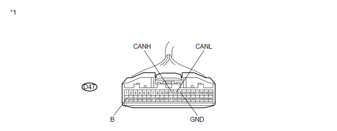
12. AIR CONDITIONING AMPLIFIER
(a) Disconnect the connector of the air conditioning amplifier.
 Text in Illustration
|
*1 |
Front view of wire harness connector (to Air Conditioning Amplifier) |
(b) Measure the resistance according to the value(s) in the table below.
Standard Resistance:
|
Terminal No. (Symbol) |
Wiring Color |
Terminal Description |
Condition |
Specified Condition |
|---|---|---|---|---|
|
D47-11 (CANH) - D47-12 (CANL) |
P - W |
HIGH-level CAN bus line - LOW-level CAN bus line |
Ignition switch off |
54 to 69 Ω |
|
D47-11 (CANH) - D47-21 (B) |
P - V |
HIGH-level CAN bus line - Battery positive (+) |
Cable disconnected from negative (-) battery terminal |
6 kΩ or higher |
|
D47-12 (CANL) - D47-21 (B) |
W - V |
LOW-level CAN bus line - Battery positive (+) |
Cable disconnected from negative (-) battery terminal |
6 kΩ or higher |
|
D47-11 (CANH) - D47-13 (GND) |
P - L |
HIGH-level CAN bus line - Ground |
Ignition switch off |
200 Ω or higher |
|
D47-12 (CANL) - D47-13 (GND) |
W - L |
LOW-level CAN bus line - Ground |
Ignition switch off |
200 Ω or higher |
13. CENTER AIRBAG SENSOR ASSEMBLY
(a) Disconnect the connector of the center airbag sensor assembly.
 Text in Illustration
|
*1 |
Front view of wire harness connector (to Center Airbag Sensor Assembly) |
|
*2 |
DLC3 |
(b) Measure the resistance according to the value(s) in the table below.
Standard Resistance:
|
Terminal No. (Symbol) |
Wiring Color |
Terminal Description |
Condition |
Specified Condition |
|---|---|---|---|---|
|
D6-13 (CANH) - D6-22 (CANL) |
SB- W |
HIGH-level CAN bus line - LOW-level CAN bus line |
Ignition switch off |
54 to 69 Ω |
|
D6-13 (CANH) - D1-16 (BAT) |
SB - LG |
HIGH-level CAN bus line - Battery positive (+) |
Cable disconnected from negative (-) battery terminal |
6 kΩ or higher |
|
D6-22 (CANL) - D1-16 (BAT) |
W - LG |
LOW-level CAN bus line - Battery positive (+) |
Cable disconnected from negative (-) battery terminal |
6 kΩ or higher |
|
D6-13 (CANH) - D6-25 (E1) |
SB - W-B |
HIGH-level CAN bus line - Ground |
Ignition switch off |
200 Ω or higher |
|
D6-22 (CANL) - D6-25 (E1) |
W - W-B |
LOW-level CAN bus line - Ground |
Ignition switch off |
200 Ω or higher |
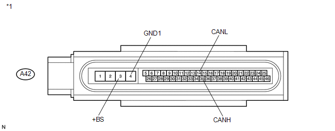
14. SKID CONTROL ECU (BRAKE ACTUATOR)
(a) Disconnect the connector of the brake actuator (skid control ECU).
 Text in Illustration
|
*1 |
Front view of wire harness connector (to Skid Control ECU) |
(b) Measure the resistance according to the value(s) in the table below.
Standard Resistance:
|
Terminal No. (Symbol) |
Wiring Color |
Terminal Description |
Condition |
Specified Condition |
|---|---|---|---|---|
|
A42-35 (CANH) - A42-14 (CANL) |
GR - W |
HIGH-level CAN bus line - LOW-level CAN bus line |
Ignition switch off |
54 to 69 Ω |
|
A42-35 (CANH) - A42-3 (+BS) |
GR - GR |
HIGH-level CAN bus line - Battery positive (+) |
Cable disconnected from negative (-) battery terminal |
6 kΩ or higher |
|
A42-14 (CANL) - A42-3 (+BS) |
W - GR |
LOW-level CAN bus line - Battery positive (+) |
Cable disconnected from negative (-) battery terminal |
6 kΩ or higher |
|
A42-35 (CANH) - A42-4 (GND1) |
GR - W |
HIGH-level CAN bus line - Ground |
Ignition switch off |
200 Ω or higher |
|
A42-14 (CANL) - A42-4 (GND1) |
W - W |
LOW-level CAN bus line - Ground |
Ignition switch off |
200 Ω or higher |
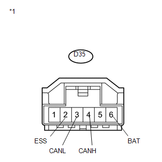
15. STEERING ANGLE SENSOR
(a) Disconnect the connector of the steering angle sensor.
 Text in Illustration
|
*1 |
Front view of wire harness connector (to Steering Angle Sensor) |
(b) Measure the resistance according to the value(s) in the table below.
Standard Resistance:
|
Terminal No. (Symbol) |
Wiring Color |
Terminal Description |
Condition |
Specified Condition |
|---|---|---|---|---|
|
D35-4 (CANH) - D35-3 (CANL) |
L - W |
HIGH-level CAN bus line - LOW-level CAN bus line |
Ignition switch off |
54 to 69 Ω |
|
D35-4 (CANH) - D35-6 (BAT) |
L - BR |
HIGH-level CAN bus line - Battery positive (+) |
Cable disconnected from negative (-) battery terminal |
6 kΩ or higher |
|
D35-3 (CANL) - D35-6 (BAT) |
W - BR |
LOW-level CAN bus line - Battery positive (+) |
Cable disconnected from negative (-) battery terminal |
6 kΩ or higher |
|
D35-4 (CANH) - D35-2 (ESS) |
L - W |
HIGH-level CAN bus line - Ground |
Ignition switch off |
200 Ω or higher |
|
D35-3 (CANL) - D35-2 (ESS) |
W - W |
LOW-level CAN bus line - Ground |
Ignition switch off |
200 Ω or higher |
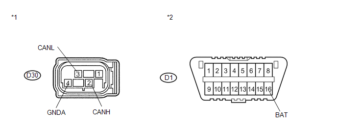
16. YAW RATE SENSOR
(a) Disconnect the connector of the yaw rate sensor.
 Text in Illustration
|
*1 |
Front view of wire harness connector (to Yaw Rate Sensor) |
|
*2 |
DLC3 |
(b) Measure the resistance according to the value(s) in the table below.
Standard Resistance:
|
Terminal No. (Symbol) |
Wiring Color |
Terminal Description |
Condition |
Specified Condition |
|---|---|---|---|---|
|
D30-2 (CANH) - D30-3 (CANL) |
V - W |
HIGH-level CAN bus line - LOW-level CAN bus line |
Ignition switch off |
54 to 69 Ω |
|
D30-2 (CANH) - D1-16 (BAT) |
V - LG |
HIGH-level CAN bus line - Battery positive (+) |
Cable disconnected from negative (-) battery terminal |
6 kΩ or higher |
|
D30-3 (CANL) - D1-16 (BAT) |
W - LG |
LOW-level CAN bus line - Battery positive (+) |
Cable disconnected from negative (-) battery terminal |
6 kΩ or higher |
|
D30-2 (CANH) - D30-4 (GNDA) |
V - B |
HIGH-level CAN bus line - Ground |
Ignition switch off |
200 Ω or higher |
|
D30-3 (CANL) - D30-4 (GNDA) |
W - B |
LOW-level CAN bus line - Ground |
Ignition switch off |
200 Ω or higher |
17. 4WD CONTROL ECU (for AWD)
(a) Disconnect the connector of the 4WD control ECU.
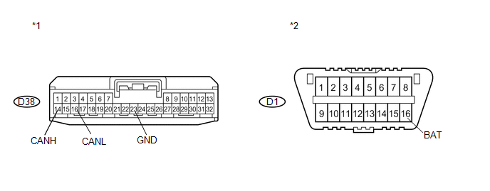 Text in Illustration
|
*1 |
Front view of wire harness connector (to 4WD Control ECU) |
|
*2 |
DLC3 |
(b) Measure the resistance according to the value(s) in the table below.
Standard Resistance:
|
Terminal No. (Symbol) |
Wiring Color |
Terminal Description |
Condition |
Specified Condition |
|---|---|---|---|---|
|
D38-14 (CANH) - D38-16 (CANL) |
L - W |
HIGH-level CAN bus line - LOW-level CAN bus line |
Ignition switch off |
54 to 69 Ω |
|
D38-14 (CANH) - D1-16 (BAT) |
L - LG |
HIGH-level CAN bus line - Battery positive (+) |
Cable disconnected from negative (-) battery terminal |
6 kΩ or higher |
|
D38-16 (CANL) - D1-16 (BAT) |
W - LG |
LOW-level CAN bus line - Battery positive (+) |
Cable disconnected from negative (-) battery terminal |
6 kΩ or higher |
|
D38-14 (CANH) - D38-23 (GND) |
L - B |
HIGH-level CAN bus line - Ground |
Ignition switch off |
200 Ω or higher |
|
D38-16 (CANL) - D38-23 (GND) |
W - B |
LOW-level CAN bus line - Ground |
Ignition switch off |
200 Ω or higher |
18. CERTIFICATION ECU (w/ Smart Key System)
(a) Disconnect the connector of the certification ECU.
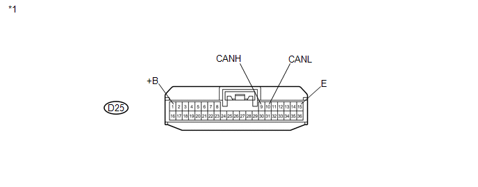 Text in Illustration
|
*1 |
Front view of wire harness connector (to Certification ECU) |
(b) Measure the resistance according to the value(s) in the table below.
Standard Resistance:
|
Terminal No. (Symbol) |
Wiring Color |
Terminal Description |
Condition |
Specified Condition |
|---|---|---|---|---|
|
D25-9 (CANH) - D25-10 (CANL) |
G - W |
HIGH-level CAN bus line - LOW-level CAN bus line |
Ignition switch off |
54 to 69 Ω |
|
D25-9 (CANH) - D25-1 (+B) |
G - G |
HIGH-level CAN bus line - Battery positive (+) |
Cable disconnected from negative (-) battery terminal |
6 kΩ or higher |
|
D25-10 (CANL) - D25-1 (+B) |
W - G |
LOW-level CAN bus line - Battery positive (+) |
Cable disconnected from negative (-) battery terminal |
6 kΩ or higher |
|
D25-9 (CANH) - D25-15 (E) |
G - B |
HIGH-level CAN bus line - Ground |
Ignition switch off |
200 Ω or higher |
|
D25-10 (CANL) - D25-15 (E) |
W - B |
LOW-level CAN bus line - Ground |
Ignition switch off |
200 Ω or higher |
19. POWER MANAGEMENT CONTROL ECU (w/ Smart Key System)
(a) Disconnect the connector of the power management control ECU.
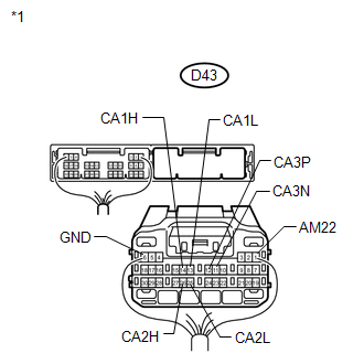 Text in Illustration
|
*1 |
Rear view of wire harness connector (to Power Management Control ECU) |
(b) Measure the resistance according to the value(s) in the table below.
Standard Resistance:
for CAN No. 1 Bus Branch Wire|
Terminal No. (Symbol) |
Wiring Color |
Terminal Description |
Condition |
Specified Condition |
|---|---|---|---|---|
|
D43-14 (CA1H) - D43-13 (CA1L) |
Y - W |
HIGH-level CAN bus line - LOW-level CAN bus line |
Ignition switch off |
54 to 69 Ω |
|
D43-14 (CA1H) - D43-1 (AM22) |
Y - LG |
HIGH-level CAN bus line - Battery positive (+) |
Cable disconnected from negative (-) battery terminal |
6 kΩ or higher |
|
D43-13 (CA1L) - D43-1 (AM22) |
W - LG |
LOW-level CAN bus line - Battery positive (+) |
Cable disconnected from negative (-) battery terminal |
6 kΩ or higher |
|
D43-14 (CA1H) - D43-6 (GND) |
Y - W |
HIGH-level CAN bus line - Ground |
Ignition switch off |
200 Ω or higher |
|
D43-13 (CA1L) - D43-6 (GND) |
W - W |
LOW-level CAN bus line - Ground |
Ignition switch off |
200 Ω or higher |
|
Terminal No. (Symbol) |
Wiring Color |
Terminal Description |
Condition |
Specified Condition |
|---|---|---|---|---|
|
D43-26 (CA2H) - D43-25 (CA2L) |
R - W |
HIGH-level CAN bus line - LOW-level CAN bus line |
Ignition switch off |
108 to 132 Ω |
|
D43-26 (CA2H) - D43-1 (AM22) |
R - LG |
HIGH-level CAN bus line - Battery positive (+) |
Cable disconnected from negative (-) battery terminal |
6 kΩ or higher |
|
D43-25 (CA2L) - D43-1 (AM22) |
W - LG |
LOW-level CAN bus line - Battery positive (+) |
Cable disconnected from negative (-) battery terminal |
6 kΩ or higher |
|
D43-26 (CA2H) - D43-6 (GND) |
R - W |
HIGH-level CAN bus line - Ground |
Ignition switch off |
200 Ω or higher |
|
D43-25 (CA2L) - D43-6 (GND) |
W - W |
LOW-level CAN bus line - Ground |
Ignition switch off |
200 Ω or higher |
|
Terminal No. (Symbol) |
Wiring Color |
Terminal Description |
Condition |
Specified Condition |
|---|---|---|---|---|
|
D43-12 (CA3P) - D43-11 (CA3N) |
G - W |
HIGH-level CAN bus line - LOW-level CAN bus line |
Ignition switch off |
108 to 132 Ω |
|
D43-12 (CA3P) - D43-1 (AM22) |
G - LG |
HIGH-level CAN bus line - Battery positive (+) |
Cable disconnected from negative (-) battery terminal |
6 kΩ or higher |
|
D43-11 (CA3N) - D43-1 (AM22) |
W - LG |
LOW-level CAN bus line - Battery positive (+) |
Cable disconnected from negative (-) battery terminal |
6 kΩ or higher |
|
D43-12 (CA3P) - D43-6 (GND) |
G - W |
HIGH-level CAN bus line - Ground |
Ignition switch off |
200 Ω or higher |
|
D43-11 (CA3N) - D43-6 (GND) |
W - W |
LOW-level CAN bus line - Ground |
Ignition switch off |
200 Ω or higher |
20. POWER BACK DOOR ECU (BACK DOOR MOTOR UNIT) (w/ Power Back Door System)
(a) Disconnect the connector of the power back door ECU (back door motor unit).
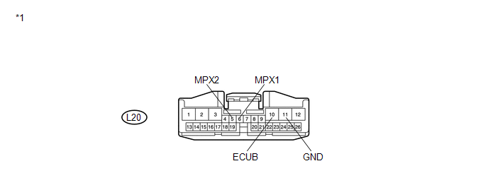 Text in Illustration
|
*1 |
Front view of wire harness connector (to Power Back Door ECU) |
(b) Measure the resistance according to the value(s) in the table below.
Standard Resistance:
|
Terminal No. (Symbol) |
Wiring Color |
Terminal Description |
Condition |
Specified Condition |
|---|---|---|---|---|
|
L20-6 (MPX1) - L20-5 (MPX2) |
P - W |
HIGH-level CAN bus line - LOW-level CAN bus line |
Ignition switch off |
54 to 69 Ω |
|
L20-6 (MPX1) - L20-10 (ECUB) |
P - P |
HIGH-level CAN bus line - Battery positive (+) |
Cable disconnected from negative (-) battery terminal |
6 kΩ or higher |
|
L20-5 (MPX2) - L20-10 (ECUB) |
W - P |
LOW-level CAN bus line - Battery positive (+) |
Cable disconnected from negative (-) battery terminal |
6 kΩ or higher |
|
L20-6 (MPX1) - L20-11 (GND) |
P - W-B |
HIGH-level CAN bus line - Ground |
Ignition switch off |
200 Ω or higher |
|
L20-5 (MPX2) - L20-11 (GND) |
W - W-B |
LOW-level CAN bus line - Ground |
Ignition switch off |
200 Ω or higher |
21. BACK DOOR CLOSER ECU (w/ Back Door Closer System)
(a) Disconnect the connector of the back door closer ECU.
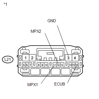 Text in Illustration
|
*1 |
Front view of wire harness connector (to Back Door Closer ECU) |
(b) Measure the resistance according to the value(s) in the table below.
Standard Resistance:
|
Terminal No. (Symbol) |
Wiring Color |
Terminal Description |
Condition |
Specified Condition |
|---|---|---|---|---|
|
L21-11 (MPX1) - L21-12 (MPX2) |
P - W |
HIGH-level CAN bus line - LOW-level CAN bus line |
Ignition switch off |
54 to 69 Ω |
|
L21-11 (MPX1) - L21-16 (ECUB) |
P - P |
HIGH-level CAN bus line - Battery positive (+) |
Cable disconnected from negative (-) battery terminal |
6 kΩ or higher |
|
L21-12 (MPX2) - L21-16 (ECUB) |
W - P |
LOW-level CAN bus line - Battery positive (+) |
Cable disconnected from negative (-) battery terminal |
6 kΩ or higher |
|
L21-11 (MPX1) - L21-3 (GND) |
P - W-B |
HIGH-level CAN bus line - Ground |
Ignition switch off |
200 Ω or higher |
|
L21-12 (MPX2) - L21-3 (GND) |
W - W-B |
LOW-level CAN bus line - Ground |
Ignition switch off |
200 Ω or higher |
22. AFS ECU (w/ HID Headlight)
(a) Disconnect the connector of the AFS ECU.
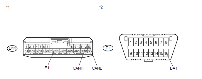 Text in Illustration
|
*1 |
Front view of wire harness connector (to AFS ECU) |
|
*2 |
DLC3 |
(b) Measure the resistance according to the value(s) in the table below.
Standard Resistance:
|
Terminal No. (Symbol) |
Wiring Color |
Terminal Description |
Condition |
Specified Condition |
|---|---|---|---|---|
|
D44-12 (CANH) - D44-13 (CANL) |
Y - W |
HIGH-level CAN bus line - LOW-level CAN bus line |
Ignition switch off |
54 to 69 Ω |
|
D44-12 (CANH) - D1-16 (BAT) |
Y - LG |
HIGH-level CAN bus line - Battery positive (+) |
Cable disconnected from negative (-) battery terminal |
6 kΩ or higher |
|
D44-13 (CANL) - D1-16 (BAT) |
W - LG |
LOW-level CAN bus line - Battery positive (+) |
Cable disconnected from negative (-) battery terminal |
6 kΩ or higher |
|
D44-12 (CANH) - D44-22 (E1) |
Y - B |
HIGH-level CAN bus line - Ground |
Ignition switch off |
200 Ω or higher |
|
D44-13 (CANL) - D44-22 (E1) |
W - B |
LOW-level CAN bus line - Ground |
Ignition switch off |
200 Ω or higher |
23. OUTER MIRROR CONTROL ECU ASSEMBLY (for Driver Side) (w/ Seat Position Memory System)
(a) Disconnect the connector of the outer mirror control ECU assembly.
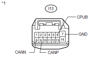 Text in Illustration
|
*1 |
Front view of wire harness connector (to Outer Mirror Control ECU Assembly (for Driver Side)) |
(b) Measure the resistance according to the value(s) in the table below.
Standard Resistance:
|
Terminal No. (Symbol) |
Wiring Color |
Terminal Description |
Condition |
Specified Condition |
|---|---|---|---|---|
|
I13-9 (CANP) - I13-8 (CANN) |
L - W |
HIGH-level CAN bus line - LOW-level CAN bus line |
Ignition switch off |
54 to 69 Ω |
|
I13-9 (CANP) - I13-6 (CPUB) |
L - LG |
HIGH-level CAN bus line - Battery positive (+) |
Cable disconnected from negative (-) battery terminal |
6 kΩ or higher |
|
I13-8 (CANN) - I13-6 (CPUB) |
W - LG |
LOW-level CAN bus line - Battery positive (+) |
Cable disconnected from negative (-) battery terminal |
6 kΩ or higher |
|
I13-9 (CANP) - I13-7 (GND) |
L - W-B |
HIGH-level CAN bus line - Ground |
Ignition switch off |
200 Ω or higher |
|
I13-8 (CANN) - I13-7 (GND) |
W - W-B |
LOW-level CAN bus line - Ground |
Ignition switch off |
200 Ω or higher |
24. OUTER MIRROR CONTROL ECU ASSEMBLY (for Front Passenger Side) (w/ Seat Position Memory System)
(a) Disconnect the connector of the outer mirror control ECU assembly.
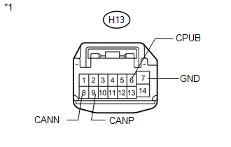 Text in Illustration
|
*1 |
Front view of wire harness connector (to Outer Mirror Control ECU Assembly (for Front Passenger Side)) |
(b) Measure the resistance according to the value(s) in the table below.
Standard Resistance:
|
Terminal No. (Symbol) |
Wiring Color |
Terminal Description |
Condition |
Specified Condition |
|---|---|---|---|---|
|
H13-9 (CANP) - H13-8 (CANN) |
P - W |
HIGH-level CAN bus line - LOW-level CAN bus line |
Ignition switch off |
54 to 69 Ω |
|
H13-9 (CANP) - H13-6 (CPUB) |
P - B |
HIGH-level CAN bus line - Battery positive (+) |
Cable disconnected from negative (-) battery terminal |
6 kΩ or higher |
|
H13-8 (CANN) - H13-6 (CPUB) |
W - B |
LOW-level CAN bus line - Battery positive (+) |
Cable disconnected from negative (-) battery terminal |
6 kΩ or higher |
|
H13-9 (CANP) - H13-7 (GND) |
P - W-B |
HIGH-level CAN bus line - Ground |
Ignition switch off |
200 Ω or higher |
|
H13-8 (CANN) - H13-7 (GND) |
W - W-B |
LOW-level CAN bus line - Ground |
Ignition switch off |
200 Ω or higher |
25. POSITION CONTROL ECU AND SWITCH ASSEMBLY (w/ Seat Position Memory System)
(a) Disconnect the connectors of the position control ECU and switch assembly.
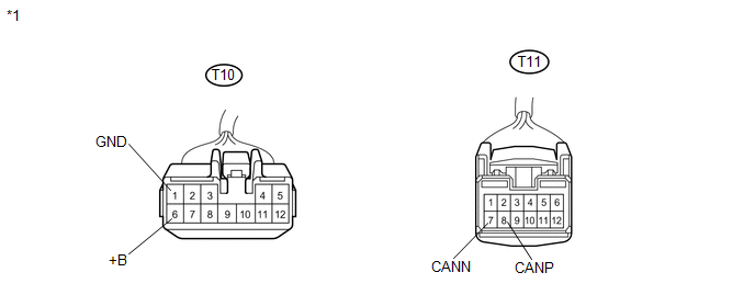 Text in Illustration
|
*1 |
Front view of wire harness connector (to Position Control ECU and Switch Assembly) |
(b) Measure the resistance according to the value(s) in the table below.
Standard Resistance:
|
Terminal No. (Symbol) |
Wiring Color |
Terminal Description |
Condition |
Specified Condition |
|---|---|---|---|---|
|
T11-8 (CANP) - T11-7 (CANN) |
G - R |
HIGH-level CAN bus line - LOW-level CAN bus line |
Ignition switch off |
54 to 69 Ω |
|
T11-8 (CANP) - T10-6 (+B) |
G - L |
HIGH-level CAN bus line - Battery positive (+) |
Cable disconnected from negative (-) battery terminal |
6 kΩ or higher |
|
T11-7 (CANN) - T10-6 (+B) |
R - L |
LOW-level CAN bus line - Battery positive (+) |
Cable disconnected from negative (-) battery terminal |
6 kΩ or higher |
|
T11-8 (CANP) - T10-1 (GND) |
G - W |
HIGH-level CAN bus line - Ground |
Ignition switch off |
200 Ω or higher |
|
T11-7 (CANN) - T10-1 (GND) |
R - W |
LOW-level CAN bus line - Ground |
Ignition switch off |
200 Ω or higher |
26. NAVIGATION RECEIVER ASSEMBLY (for Navigation System)
(a) Disconnect the connectors of the navigation receiver assembly.
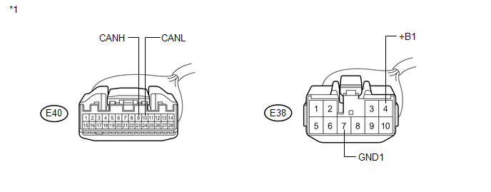 Text in Illustration
|
*1 |
Front view of wire harness connector (to Navigation Receiver Assembly) |
(b) Measure the resistance according to the value(s) in the table below.
Standard Resistance:
|
Terminal No. (Symbol) |
Wiring Color |
Terminal Description |
Condition |
Specified Condition |
|---|---|---|---|---|
|
E40-9 (CANH) - E40-10 (CANL) |
SB - W |
HIGH-level CAN bus line - LOW-level CAN bus line |
Ignition switch off |
54 to 69 Ω |
|
E40-9 (CANH) - E38-4 (+B1) |
SB - SB |
HIGH-level CAN bus line - Battery positive (+) |
Cable disconnected from negative (-) battery terminal |
6 kΩ or higher |
|
E40-10 (CANL) - E38-4 (+B1) |
W - SB |
LOW-level CAN bus line - Battery positive (+) |
Cable disconnected from negative (-) battery terminal |
6 kΩ or higher |
|
E40-9 (CANH) - E38-7 (GND1) |
SB - BR |
HIGH-level CAN bus line - Ground |
Ignition switch off |
200 Ω or higher |
|
E40-10 (CANL) - E38-7 (GND1) |
W - BR |
LOW-level CAN bus line - Ground |
Ignition switch off |
200 Ω or higher |
27. RADIO AND DISPLAY RECEIVER ASSEMBLY (for Audio and Visual System)
(a) Disconnect the connectors of the radio and display receiver assembly.
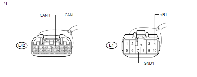 Text in Illustration
|
*1 |
Front view of wire harness connector (to Radio and Display Receiver Assembly) |
(b) Measure the resistance according to the value(s) in the table below.
Standard Resistance:
|
Terminal No. (Symbol) |
Wiring Color |
Terminal Description |
Condition |
Specified Condition |
|---|---|---|---|---|
|
E42-9 (CANH) - E42-10 (CANL) |
SB - W |
HIGH-level CAN bus line - LOW-level CAN bus line |
Ignition switch off |
54 to 69 Ω |
|
E42-9 (CANH) - E4-4 (+B1) |
SB - SB |
HIGH-level CAN bus line - Battery positive (+) |
Cable disconnected from negative (-) battery terminal |
6 kΩ or higher |
|
E42-10 (CANL) - E4-4 (+B1) |
W - SB |
LOW-level CAN bus line - Battery positive (+) |
Cable disconnected from negative (-) battery terminal |
6 kΩ or higher |
|
E42-9 (CANH) - E4-7 (GND1) |
SB - BR |
HIGH-level CAN bus line - Ground |
Ignition switch off |
200 Ω or higher |
|
E42-10 (CANL) - E4-7 (GND1) |
W - BR |
LOW-level CAN bus line - Ground |
Ignition switch off |
200 Ω or higher |
28. CLEARANCE WARNING ECU ASSEMBLY (w/ Intuitive Parking Assist System)
(a) Disconnect the connector of the clearance warning ECU assembly.
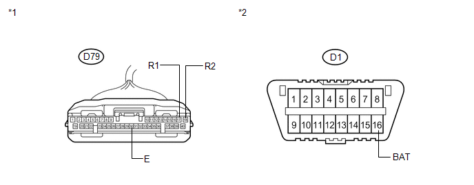 Text in Illustration
|
*1 |
Front view of wire harness connector (to Clearance Warning ECU Assembly) |
|
*2 |
DLC3 |
(b) Measure the resistance according to the value(s) in the table below.
Standard Resistance:
|
Terminal No. (Symbol) |
Wiring Color |
Terminal Description |
Condition |
Specified Condition |
|---|---|---|---|---|
|
D79-17 (R1) - D79-18 (R2) |
R - W |
HIGH-level CAN bus line - LOW-level CAN bus line |
Ignition switch off |
54 to 69 Ω |
|
D79-17 (R1) - D1-16 (BAT) |
R - LG |
HIGH-level CAN bus line - Battery positive (+) |
Cable disconnected from negative (-) battery terminal |
6 kΩ or higher |
|
D79-18 (R2) - D1-16 (BAT) |
W - LG |
LOW-level CAN bus line - Battery positive (+) |
Cable disconnected from negative (-) battery terminal |
6 kΩ or higher |
|
D79-17 (R1) - D79-30 (E) |
R - W |
HIGH-level CAN bus line - Ground |
Ignition switch off |
200 Ω or higher |
|
D79-18 (R2) - D79-30 (E) |
W - W |
LOW-level CAN bus line - Ground |
Ignition switch off |
200 Ω or higher |
 Problem Symptoms Table
PROBLEM SYMPTOMS TABLE
HINT:
Use the table below to help determine the cause of problem symptoms.
If multiple suspected areas are listed, the potential causes of the symptoms
are lis ...
 Diagnosis System
DIAGNOSIS SYSTEM
1. ECUS OR SENSORS WHICH COMMUNICATE THROUGH CAN COMMUNICATION SYSTEM
(a) CAN No. 1 Bus
(1) ECM
(2) Main body ECU (Driver side junction block)
(3) Combination meter
(4) Power st ...
Other materials about Toyota Venza:
ECM / PCM Internal Engine Off Timer Performance (P2610)
DTC SUMMARY
DTC No.
Monitoring Item
Malfunction Detection Condition
Trouble Area
Detection Timing
Detection Logic
P2610
Soak timer (built into ECM)
An ECM ...
Diagnosis System
DIAGNOSIS SYSTEM
1. DESCRIPTION
(a) The transponder key ECU assembly controls the vehicle's immobiliser system
functions. Immobiliser system data and Diagnostic Trouble Code (DTC) can be read
through the vehicle's Data Link Connector 3 (DLC3).
I ...
Rear Right Center Sensor Malfunction (C1AE8)
DESCRIPTION
The No. 1 ultrasonic sensor (rear right center sensor) is installed on the rear
bumper. The ECU detects obstacles based on signals received from the No. 1 ultrasonic
sensor (rear right center sensor). If the No. 1 ultrasonic sensor (rear right ...

0.1541