Toyota Venza: Open in Rear Floor Electrical Key Oscillator Circuit (B27A6)
DESCRIPTION
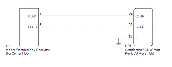
The certification ECU (smart key ECU assembly) generates a request signal and sends it to the indoor electrical key oscillator (for center floor). To detect the key inside the cabin, the indoor electrical key oscillator (for center floor) creates a detection area in the cabin.
DTC B27A6 is detected by the certification ECU (smart key ECU assembly) when an open circuit occurs between the certification ECU (smart key ECU assembly) and indoor electrical key oscillator (for center floor) terminals (between CLG6 and CLG4, or CG6B and CLGB).
|
DTC No. |
DTC Detection Condition |
Trouble Area |
|---|---|---|
|
B27A6 |
Open circuit detected between the certification ECU (smart key ECU assembly) and indoor electrical key oscillator (for center floor) terminals (between CLG6 and CLG4, or CG6B and CLGB). |
|
WIRING DIAGRAM
CAUTION / NOTICE / HINT
NOTICE:
The smart key system (for entry function) uses a multiplex communication system
(LIN communication system) and CAN communication system. Inspect the communication
function by following How to Proceed with Troubleshooting (See page
.gif) ). Troubleshoot the smart key system (for entry
). Troubleshoot the smart key system (for entry
function) after confirming that the communication system is functioning properly.
PROCEDURE
|
1. |
CHECK CONNECTOR CONNECTION CONDITION |
(a) Turn the engine switch off.
(b) Check that the connectors are properly connected to the certification ECU (smart key ECU assembly) and the indoor electrical key oscillator (for center floor).
OK:
Connectors are properly connected.
| NG | .gif) |
CONNECT CONNECTORS PROPERLY |
|
.gif)
|
2. |
CHECK HARNESS AND CONNECTOR (CERTIFICATION ECU - INDOOR ELECTRICAL KEY OSCILLATOR) |
(a) Disconnect the certification ECU (smart key ECU assembly) connector.
|
(b) Disconnect the indoor electrical key oscillator (for center floor) connector. |
|
(c) Measure the resistance according to the value(s) in the table below.
Standard Resistance:
|
Tester Connection |
Condition |
Specified Condition |
|---|---|---|
|
D25-24 (CLG6) - L10-1 (CLG4) |
Always |
Below 1 Ω |
|
D25-25 (CG6B) - L10-3 (CLGB) |
Always |
Below 1 Ω |
|
D25-24 (CLG6) - Body ground |
Always |
10 kΩ or higher |
|
D25-25 (CG6B) - Body ground |
Always |
10 kΩ or higher |
|
L10-1 (CLG4) - Body ground |
Always |
10 kΩ or higher |
|
L10-3 (CLGB) - Body ground |
Always |
10 kΩ or higher |
|
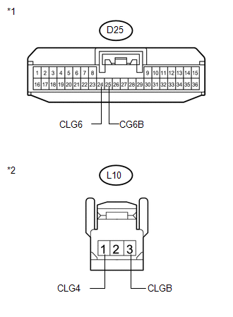
*1 |
Front view of wire harness connector (to Certification ECU (Smart Key ECU Assembly)) |
|
*2 |
Front view of wire harness connector (to Indoor Electrical Key Oscillator (for Center Floor)) |
| NG | |
REPAIR OR REPLACE HARNESS OR CONNECTOR |
|
|
3. |
INSPECT CERTIFICATION ECU (SMART KEY ECU ASSEMBLY) (INDOOR ELECTRICAL KEY OSCILLATOR SIGNAL OUTPUT) |
|
(a) Reconnect the certification ECU (smart key ECU assembly) connector. |
|
(b) Measure the resistance and check for pulses according to the value(s) in the table below.
Standard Resistance:
|
Tester Connection |
Condition |
Specified Condition |
|---|---|---|
|
D25-15 (E) - Body ground |
Always |
Below 1 Ω |
Standard:
|
Tester Connection |
Condition |
Specified Condition |
|---|---|---|
|
D25-24 (CLG6) - D25-15 (E) |
|
No pulse generation |
|
D25-24 (CLG6) - D25-15 (E) |
|
Pulse generation |
|
D25-25 (CG6B) - D25-15 (E) |
|
No pulse generation |
|
D25-25 (CG6B) - D25-15 (E) |
|
Pulse generation |
|
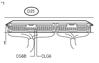
*1 |
Component with harness connected (Certification ECU (Smart Key ECU Assembly)) |
| NG | |
REPLACE CERTIFICATION ECU (SMART KEY ECU ASSEMBLY) |
|
|
4. |
REPLACE INDOOR ELECTRICAL KEY OSCILLATOR (for Center Floor) |
(a) Replace the indoor electrical key oscillator (for center floor) (See page
).
|
|
5. |
CHECK DTC OUTPUT |
(a) Clear the DTCs (See page ).
(b) Recheck for DTCs.
OK:
DTC B27A6 is not output.
| OK | |
END (INDOOR ELECTRICAL KEY OSCILLATOR WAS DEFECTIVE) |
| NG | |
REPLACE CERTIFICATION ECU (SMART KEY ECU ASSEMBLY) |
 Open in Outside Luggage Compartment Electrical Key Antenna Circuit (B27A8)
DESCRIPTION
The certification ECU (smart key ECU assembly) generates a request signal and
sends it to the outside electrical key oscillator (for rear side). To detect the
key near the driver door ...
 Open in Inside Luggage Compartment Electrical Key Oscillator Circuit (B27A7)
DESCRIPTION
The certification ECU (smart key ECU assembly) generates a request signal and
sends it to the indoor electrical key oscillator (for rear floor). To detect the
key inside the cabin, th ...
Other materials about Toyota Venza:
Removal
REMOVAL
PROCEDURE
1. ALIGN FRONT WHEELS FACING STRAIGHT AHEAD
2. DISCONNECT CABLE FROM NEGATIVE BATTERY TERMINAL
NOTICE:
When disconnecting the cable, some systems need to be initialized after the cable
is reconnected (See page ).
3. REMOVE FRONT WHEE ...
How To Proceed With Troubleshooting
CAUTION / NOTICE / HINT
HINT:
Use the following procedure to troubleshoot the windshield deicer system.
PROCEDURE
1.
VEHICLE BROUGHT TO WORKSHOP
NEXT
...
Registering ID codes
The tire pressure warning valve and transmitter is equipped with a unique ID
code. When replacing a tire pressure warning valve and transmitter, it is necessary
to register the ID code of tire pressure warning valve and transmitter. Have the
ID code regi ...

0.1592