Toyota Venza: Power Back Door Warning System does not Operate
DESCRIPTION
When the power back door warning system does not operate, one of the following may be malfunctioning: 1) power back door warning buzzer circuit, 2) wireless door lock control system or 3) power back door ECU.
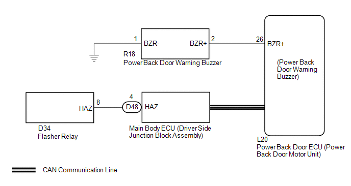
WIRING DIAGRAM
CAUTION / NOTICE / HINT
NOTICE:
- The power back door warning function can be customized. Make sure the
function is ON. (See page
.gif) )
)
- The power back door system uses a CAN communication system. Inspect
the communication function by following How to Proceed with Troubleshooting
(See page ). Troubleshoot the power back
door system after confirming that the communication system is functioning properly.
PROCEDURE
|
1. |
CHECK OPERATION |
(a) Check power back door system operation.
|
Result |
Proceed to |
|---|---|
|
Power back door warning buzzer does not operate |
A |
|
Hazard warning light does not come on |
B |
|
Power back door warning buzzer in the power back door ECU does not operate |
C |
| B | .gif) |
GO TO STEP 5 |
| C | |
REPLACE POWER BACK DOOR ECU (POWER BACK DOOR MOTOR UNIT) |
|
.gif)
|
2. |
PERFORM ACTIVE TEST USING TECHSTREAM (POWER BACK DOOR WARNING BUZZER) |
(a) Connect the Techstream to the DLC3.
(b) Turn the ignition switch to ON.
(c) Turn the Techstream on.
(d) Enter the following menus: Body Electrical / Back Door / Data List.
(e) Using the Techstream, perform the Active Test to generate a control command, and check that the power back door warning buzzer sounds.
Back Door (Power Back Door ECU)|
Tester Display |
Test Part |
Control Range |
Diagnostic Note |
|---|---|---|---|
|
PBD Buzzer |
Power back door warning buzzer sound |
ON / OFF |
- |
OK:
Buzzer sounds normally.
| OK | |
REPLACE POWER BACK DOOR ECU (POWER BACK DOOR MOTOR UNIT) |
|
|
3. |
INSPECT POWER BACK DOOR WARNING BUZZER |
|
(a) Remove the power back door warning buzzer (See page
|
|
(b) Measure the resistance according to the value(s) in the table below.
Standard Resistance:
|
Tester Connection |
Condition |
Specified Condition |
|---|---|---|
|
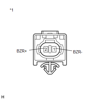
2 (BZR+) - 1(BZR-) |
Always |
950 to 1050 Ω |
|
*1 |
Component without harness connected (Power Back Door Warning Buzzer) |
| NG | |
REPLACE POWER BACK DOOR WARNING BUZZER |
|
|
4. |
CHECK HARNESS AND CONNECTOR (POWER BACK DOOR WARNING BUZZER - POWER BACK DOOR ECU) |
(a) Disconnect the R18 power back door warning buzzer connector and L20 power back door ECU connector.
(b) Disconnect the resistance according to the value(s) in the table below.
Standard Resistance:
|
Tester Connection |
Condition |
Specified Condition |
|---|---|---|
|
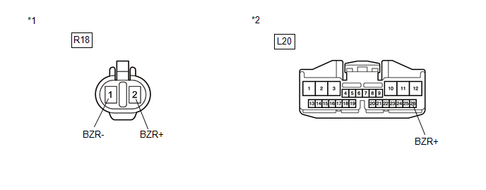
R18-2 (BZR+) - L20-26 (BZR+) |
Always |
Below 1 Ω |
|
R18-1 (BZR-) - Body ground |
Always |
Below 1 Ω |
|
R18-2 (BZR+) - Body ground |
Always |
10 kΩ or higher |
|
*1 |
Front view of wire harness connector (to Power Back Door Warning Buzzer) |
|
*2 |
Front view of wire harness connector (to Power Back Door ECU) |
| OK | |
REPLACE POWER BACK DOOR ECU (POWER BACK DOOR MOTOR UNIT) |
| NG | |
REPAIR OR REPLACE HARNESS OR CONNECTOR |
|
5. |
CHECK WIRELESS DOOR LOCK CONTROL SYSTEM (HAZARD ANSWER-BACK FUNCTION) |
(a) Check wireless door lock operation.
|
Result |
Proceed to |
|---|---|
|
Hazard answer-back function operates normally |
A |
|
Hazard answer-back function does not operate (w/ Smart Key System) |
B |
|
Hazard answer-back function does not operate (w/o Smart Key System) |
C |
| B | |
GO TO WIRELESS DOOR LOCK CONTROL SYSTEM (w/ Smart Key System) (NO ANSWER-BACK) |
| C | |
GO TO WIRELESS DOOR LOCK CONTROL SYSTEM (w/o Smart Key System) (NO ANSWER-BACK) |
|
|
6. |
REPLACE POWER BACK DOOR MOTOR UNIT (POWER BACK DOOR ECU) |
(a) Replace the power back door ECU (power back door motor unit) (See page
).
|
|
7. |
CHECK POWER BACK DOOR OPERATION |
(a) Check that the power back door hazard warning lights operate normally (See
page ).
OK:
The power back door hazard warning lights operate normally.
| OK | |
END (POWER BACK DOOR ECU (POWER BACK DOOR MOTOR UNIT) WAS DEFECTIVE) |
| NG | |
REPLACE MAIN BODY ECU (DRIVER SIDE JUNCTION BLOCK ASSEMBLY) |
 Jam Protection Function Activates During Power Back Door Operation
DESCRIPTION
When the jam protection function activates during power back door operation,
one of the following may be the cause: 1) improper fit of back door, or a foreign
object is stuck in the b ...
 Touch Sensor Circuit
DESCRIPTION
When the power back door ECU receives a jam signal from the touch sensor while
the power back door is operating, the ECU reverses the back door operation and opens
the door.
WIRING D ...
Other materials about Toyota Venza:
If your vehicle has to be stopped in an emergency
Only in an emergency, such as if it becomes impossible to stop the vehicle
in the normal way, stop the vehicle using the following procedure:
Steadily step on the brake pedal
with both feet and firmly depress it.
Do not pump the brake pedal repeatedly a ...
Power Window Master Switch
Components
COMPONENTS
ILLUSTRATION
Removal
REMOVAL
PROCEDURE
1. REMOVE POWER WINDOW REGULATOR MASTER SWITCH ASSEMBLY WITH FRONT DOOR ARMREST
BASE PANEL
2. REMOVE POWER WINDOW REGULATOR MASTER SWITCH ASSEMBLY
(a) Remove the 3 screw ...
How To Proceed With Troubleshooting
CAUTION / NOTICE / HINT
HINT:
*: Use the Techstream.
PROCEDURE
1.
VEHICLE BROUGHT TO WORKSHOP
NEXT
2.
CUSTOMER PROBLEM ANALYSIS
...

0.1608