Toyota Venza: Inspection
INSPECTION
PROCEDURE
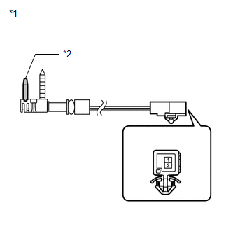
1. INSPECT EVAPORATOR TEMPERATURE SENSOR
(a) Measure the resistance according to the value(s) in the table below.
.png)
Standard Resistance:
|
Tester Connection |
Condition |
Specified Condition |
|---|---|---|
|
1 - 2 |
-10°C (14°F) |
7.30 to 9.10 kΩ |
|
1 - 2 |
-5°C (23°F) |
5.65 to 6.95 kΩ |
|
1 - 2 |
0°C (32°F) |
4.40 to 5.35 kΩ |
|
1 - 2 |
5°C (41°F) |
3.40 to 4.15 kΩ |
|
1 - 2 |
10°C (50°F) |
2.70 to 3.25 kΩ |
|
1 - 2 |
15°C (59°F) |
2.14 to 2.58 kΩ |
|
1 - 2 |
20°C (68°F) |
1.71 to 2.05 kΩ |
|
1 - 2 |
25°C (77°F) |
1.38 to 1.64 kΩ |
|
1 - 2 |
30°C (86°F) |
1.11 to 1.32 kΩ |
NOTICE:
- Hold the sensor only by its connector. Touching the sensor may change the resistance value.
- When measuring, the sensor temperature must be the same as the ambient temperature.
HINT:
As the temperature increases, the resistance decreases (see the graph).
If the resistance is not as specified, replace the evaporator temperature sensor.
Text in Illustration|
*1 |
Component without harness connected (Evaporator Temperature Sensor) |
|
*2 |
Sensing Portion |
 Removal
REMOVAL
PROCEDURE
1. REMOVE AIR CONDITIONING UNIT ASSEMBLY
(See page )
2. REMOVE NO. 1 FINISH PANEL MOUNTING BRACKET
3. REMOVE NO. 2 FINISH PANEL MOUNTING BRACKET
4. REMOVE NO. 3 AIR DUCT ...
 Installation
INSTALLATION
PROCEDURE
1. INSTALL NO. 1 COOLER THERMISTOR
(a) Install the No. 1 cooler thermistor as shown in the illustration.
Part
Length
...
Other materials about Toyota Venza:
Diagnosis System
DIAGNOSIS SYSTEM
1. DESCRIPTION
(a) Lighting system data and the Diagnostic Trouble Codes (DTCs) can be read
from the Data Link Connector 3 (DLC3) of the vehicle. When the system seems to be
malfunctioning, use the Techstream to check for malfunctions an ...
Disassembly
DISASSEMBLY
PROCEDURE
1. REMOVE STEERING RACK BOOT CLIP (for LH Side)
(a) Using pliers, remove the steering rack boot clip.
2. REMOVE STEERING RACK BOOT CLIP (for RH Side)
HINT:
Perform the same procedure as for the LH side.
3. REMOVE NO. 2 STEERING RAC ...
System Diagram
SYSTEM DIAGRAM
Communication Table
Sender
Receiver
Signal
Communication Method
Center airbag sensor assembly
Combination meter assembly
Front seat inner belt buckl ...

0.1584