Toyota Venza: Touch Sensor Circuit
DESCRIPTION
When the power back door ECU receives a jam signal from the touch sensor while the power back door is operating, the ECU reverses the back door operation and opens the door.
WIRING DIAGRAM
.png)
PROCEDURE
|
1. |
READ VALUE USING TECHSTREAM (POWER BACK DOOR TOUCH SENSOR) |
(a) Connect the Techstream to the DLC3.
(b) Turn the ignition switch to ON.
(c) Turn the Techstream on.
(d) Enter the following menus: Body Electrical / Back Door / Data List.
(e) Check the Data List for proper functioning of the power back door touch sensor.
Back Door (Power back door ECU)|
Tester Display |
Measurement Item/Range |
Normal Condition |
Diagnostic Note |
|---|---|---|---|
|
PBD Touch Sensor (Right) |
Power back door touch sensor RH signal / ON, OFF or Open |
ON: Power back door touch sensor RH pressed OFF: Power back door touch sensor RH not pressed Open: Power back door touch sensor RH circuit open |
- |
|
PBD Touch Sensor (Left) |
Power back door touch sensor LH signal / ON, OFF or Open |
ON: Power back door touch sensor LH pressed OFF: Power back door touch sensor LH not pressed Open: Power back door touch sensor LH circuit open |
- |
|
Result |
Proceed to |
|---|---|
|
ON and OFF function is normal |
A |
|
ON and OFF function is not normal, or Open is displayed for LH touch sensor |
B |
|
ON and OFF function is not normal, or Open is displayed for RH touch sensor |
C |
| A | .gif) |
END |
| C | |
GO TO STEP 5 |
|
.gif)
|
2. |
CHECK POWER BACK DOOR TOUCH SENSOR LH (POWER BACK DOOR TOUCH SENSOR LH - BODY GROUND) |
|
(a) Disconnect the R3 power back door touch sensor LH connector. |
|
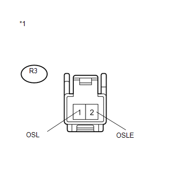
(b) Measure the resistance according to the value(s) in the table below.
Standard Resistance:
|
Tester Connection |
Condition |
Specified Condition |
|---|---|---|
|
1 (OSL) - Body ground |
Always |
10 kΩ or higher |
|
2 (OSLE) - Body ground |
Always |
10 kΩ or higher |
|
*1 |
Component without harness connected (Power Back Door Touch Sensor LH) |
HINT:
Perform this inspection with the touch sensor installed on the vehicle.
| NG | |
REPLACE POWER BACK DOOR TOUCH SENSOR LH |
|
|
3. |
INSPECT POWER BACK DOOR TOUCH SENSOR LH |
(a) Remove the power back door touch sensor LH (See page
.gif) ).
).

(b) Measure the resistance according to the value(s) in the table below.
Standard Resistance:
|
Tester Connection |
Condition |
Specified Condition |
|---|---|---|
|
1 (OSL) - 2 (OSLE) |
Not pressed |
950 to 1050 Ω |
|
1 (OSL) - 2 (OSLE) |
Pressed |
Below 100 Ω |
| NG | |
REPLACE POWER BACK DOOR TOUCH SENSOR LH |
|
|
4. |
CHECK HARNESS AND CONNECTOR (TOUCH SENSOR LH - POWER BACK DOOR ECU AND BODY GROUND) |
|
(a) Disconnect the R3 power back door touch sensor LH connector and L20 power back door ECU connector. |
|

(b) Measure the resistance according to the value(s) in the table below.
Standard Resistance:
|
Tester Connection |
Condition |
Specified Condition |
|---|---|---|
|
R3-1 (OSL) - L20-15 (OSL) |
Always |
Below 1 Ω |
|
R3-2 (OSLE) - L20-14 (OSE) |
Always |
Below 1 Ω |
|
R3-1 (OSL) - Body ground |
Always |
10 kΩ or higher |
|
*1 |
Front view of wire harness connector (to Power Back Door Touch Sensor LH) |
|
*2 |
Front view of wire harness connector (to Power Back Door ECU) |
| OK | |
REPLACE POWER BACK DOOR ECU (POWER BACK DOOR MOTOR UNIT) |
| NG | |
REPAIR OR REPLACE HARNESS OR CONNECTOR |
|
5. |
CHECK POWER BACK DOOR TOUCH SENSOR RH (POWER BACK DOOR TOUCH SENSOR RH - BODY GROUND) |
|
(a) Disconnect the R4 power back door touch sensor RH connector. |
|
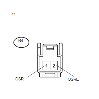
(b) Measure the resistance according to the value(s) in the table below.
Standard Resistance:
|
Tester Connection |
Condition |
Specified Condition |
|---|---|---|
|
1 (OSR) - Body ground |
Always |
10 kΩ or higher |
|
2 (OSRE) - Body ground |
Always |
10 kΩ or higher |
|
*1 |
Component without harness connected (Power Back Door Touch Sensor RH) |
HINT:
Perform this inspection with the touch sensor installed on the vehicle.
| NG | |
REPLACE POWER BACK DOOR TOUCH SENSOR RH |
|
|
6. |
INSPECT POWER BACK DOOR TOUCH SENSOR RH |
(a) Remove the power back door touch sensor RH (See page
).
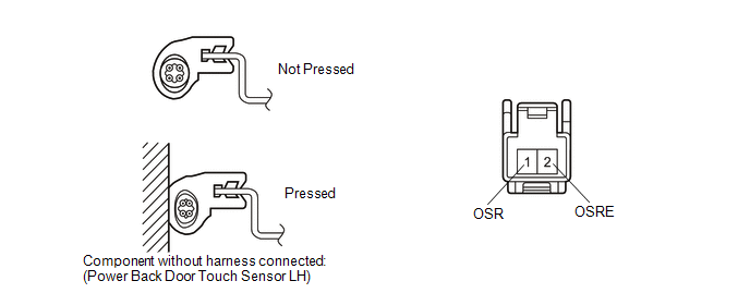
Measure the resistance according to the value(s) in the table below.
Standard Resistance:
|
Tester Connection |
Condition |
Specified Condition |
|---|---|---|
|
1 (OSR) - 2 (OSRE) |
Not pressed |
950 to 1050 Ω |
|
1 (OSR) - 2 (OSRE) |
Pressed |
Below 100 Ω |
| NG | |
REPLACE POWER BACK DOOR TOUCH SENSOR RH |
|
|
7. |
CHECK HARNESS AND CONNECTOR (TOUCH SENSOR RH - POWER BACK DOOR ECU AND BODY GROUND) |
|
(a) Disconnect the R4 power back door touch sensor RH connector and L20 power back door ECU connector. |
|
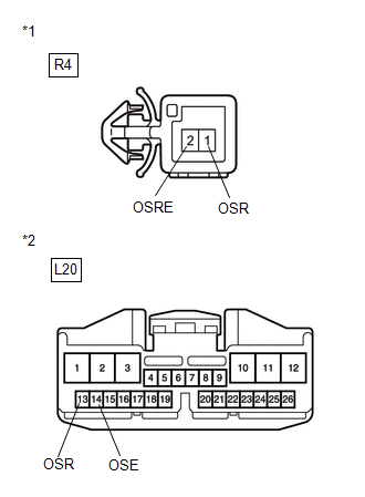
(b) Measure the resistance according to the value(s) in the table below.
Standard Resistance:
|
Tester Connection |
Condition |
Specified Condition |
|---|---|---|
|
R4-1 (OSR) - L20-13 (OSR) |
Always |
Below 1 Ω |
|
R4-2 (OSRE) - L20-14 (OSE) |
Always |
Below 1 Ω |
|
R4-1 (OSR) - Body ground |
Always |
10 kΩ or higher |
|
*1 |
Front view of wire harness connector (to Power Back Door Touch Sensor RH) |
|
*2 |
Front view of wire harness connector (to Power Back Door ECU) |
| OK | |
REPLACE POWER BACK DOOR ECU (POWER BACK DOOR MOTOR UNIT) |
| NG | |
REPAIR OR REPLACE HARNESS OR CONNECTOR |
 Power Back Door Warning System does not Operate
DESCRIPTION
When the power back door warning system does not operate, one of the following
may be malfunctioning: 1) power back door warning buzzer circuit, 2) wireless door
lock control system o ...
 Power Back Door Touch Sensor
Components
COMPONENTS
ILLUSTRATION
Removal
REMOVAL
PROCEDURE
1. REMOVE UPPER BACK WINDOW PANEL TRIM
2. REMOVE BACK DOOR PANEL TRIM ASSEMBLY
3. DISCONNECT POWER BACK DOOR ROD (for L ...
Other materials about Toyota Venza:
Personal Light
Components
COMPONENTS
ILLUSTRATION
Removal
REMOVAL
PROCEDURE
1. REMOVE MAP LIGHT ASSEMBLY
(a) Using a moulding remover, disengage the 2 claws and 2 clips.
Text in Illustration
*1
Fastener
...
Solar Sensor
Components
COMPONENTS
ILLUSTRATION
On-vehicle Inspection
ON-VEHICLE INSPECTION
PROCEDURE
1. INSPECT SOLAR SENSOR
(a) Disconnect the solar sensor connector.
(b) Measure the voltage accordin ...
Components
COMPONENTS
ILLUSTRATION
ILLUSTRATION
ILLUSTRATION
ILLUSTRATION
ILLUSTRATION
...

0.1407