Toyota Venza: Power Back Door Closer Switch
Components
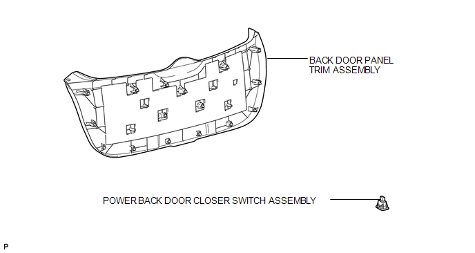
COMPONENTS
ILLUSTRATION
Removal
REMOVAL
PROCEDURE
1. REMOVE BACK DOOR PANEL TRIM ASSEMBLY
.gif)
2. REMOVE POWER BACK DOOR CLOSER SWITCH ASSEMBLY
|
(a) Disconnect the connector. |
|
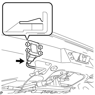
(b) Disengage the 4 claws and remove the power back door closer switch assembly.
Inspection
INSPECTION
PROCEDURE
1. INSPECT POWER BACK DOOR CLOSER SWITCH
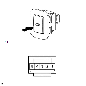
(a) Check that the switch function.
(1) Measure the resistance according to the value(s) in the table below.
Standard Resistance:
|
Tester Connection |
Condition |
Specified Condition |
|---|---|---|
|
4 - 1 |
Pushed (ON) |
Below 1 Ω |
|
4 - 1 |
Free (OFF) |
10 kΩ or higher |
|
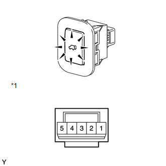
*1 |
Component without harness connected (Power Back Door Closer Switch) |
If the result is not as specified, replace the switch.
|
(b) Check that the switch illuminates. (1) Apply battery voltage to the power back door closer switch and check that the switch illuminates. OK:
If the result is not as specified, replace the switch. |
|
Installation
INSTALLATION
PROCEDURE
1. INSTALL POWER BACK DOOR CLOSER SWITCH ASSEMBLY
|
(a) Engage the 4 claws to install the power back door closer switch assembly. |
|
.png)
(b) Connect the connector.
2. INSTALL BACK DOOR PANEL TRIM ASSEMBLY
.gif)
 Removal
REMOVAL
PROCEDURE
1. REMOVE FRONT WHEEL LH
2. REMOVE FRONT FENDER OUTSIDE MOULDING LH
3. REMOVE FRONT FENDER LINER LH
(a) Using a screwdriver, turn the pin 90 degrees and remove the ...
 Power Back Door Control Switch
Components
COMPONENTS
ILLUSTRATION
Inspection
INSPECTION
PROCEDURE
1. INSPECT POWER BACK DOOR OPENER / CLOSER SWITCH
(a) Measure the resistance of the switch.
Standard resistance:
...
Other materials about Toyota Venza:
Short in Driver Side Squib Circuit (B1800/51-B1803/51)
DESCRIPTION
The driver side squib circuit consists of the center airbag sensor assembly,
spiral cable and steering pad.
The center airbag sensor assembly uses this circuit to deploy the airbag when
deployment conditions are met.
These DTCs are stored wh ...
Using the AUX port/USB port
This port can be used to connect a portable audio device and listen to it
through the vehicle’s speakers.
Open the cover.
Connect the portable audio device.
- Operating portable audio devices connected to the audio system
The volume can be adj ...
Vehicle Speed Signal Malfunction (B2282)
DESCRIPTION
The power management control ECU receives vehicle speed information using 2 methods.
It receives a speed signal from the meter ECU. It also receives speed information
from the meter ECU via CAN. If the information sent using these 2 methods is ...

0.1445