Toyota Venza: Wireless Door Lock Tuner Circuit Malfunction (B1242)
DESCRIPTION
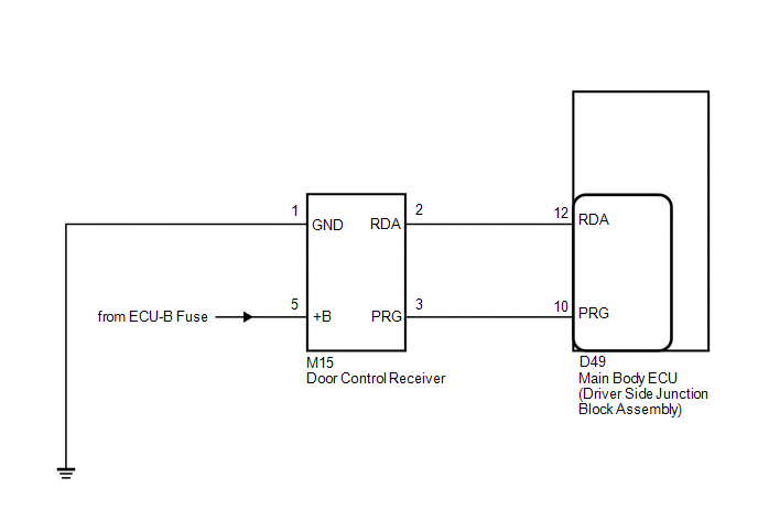
The door control receiver receives signals from the transmitter and sends these signals to the main body ECU (driver side junction block assembly).
|
DTC No. |
DTC Detection Condition |
Trouble Area |
|---|---|---|
|
B1242 |
In diagnostic mode, an applicable RDA signal cannot be received within 2.4 seconds after a PRG signal has been output from the main body ECU (driver side junction block assembly). |
|
WIRING DIAGRAM
PROCEDURE
|
1. |
CHECK HARNESS AND CONNECTOR (MAIN BODY ECU - DOOR CONTROL RECEIVER) |
|
(a) Disconnect the D49 main body ECU connector and the M15 door control receiver connector. |
|
(b) Measure the resistance according to the value(s) in the table below.
Standard Resistance:
|
Tester Connection |
Condition |
Specified Condition |
|---|---|---|
|
D49-12 (RDA) - M15-2 (RDA) |
Always |
Below 1 Ω |
|
D49-12 (RDA) - Body ground |
Always |
10 kΩ or higher |
|
D49-10 (PRG) - M15-3 (PRG) |
Always |
Below 1 Ω |
|
D49-10 (PRG) - Body ground |
Always |
10 kΩ or higher |
|
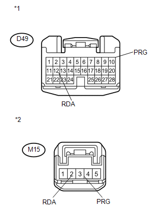
*1 |
Front view of wire harness connector (to Main Body ECU (Driver Side Junction Block Assembly)) |
|
*2 |
Front view of wire harness connector (to Door Control Receiver) |
| NG | .gif) |
REPAIR OR REPLACE HARNESS OR CONNECTOR |
|
.gif)
|
2. |
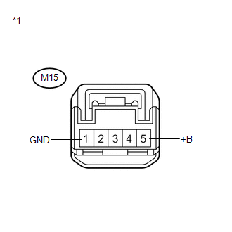
CHECK HARNESS AND CONNECTOR (BATTERY, BODY GROUND) |
|
(a) Measure the voltage and resistance according to the value(s) in the table below. Standard:
|
|
| NG | |
REPAIR OR REPLACE HARNESS OR CONNECTOR |
|
|
3. |
REPLACE DOOR CONTROL RECEIVER |
(a) Temporarily replace the door lock control receiver with a new or known good
one (See page .gif) ).
).
|
|
4. |
REGISTER RECOGNITION CODE |
(a) Perform the Registration procedure (See page
).
|
|
5. |
CONFIRM DTC |
(a) Clear the DTCs (See page ).
(b) Recheck for DTCs.
|
Result |
Proceed to |
|---|---|
|
DTC is not output |
A |
|
DTC is output |
B |
| A | |
END (DOOR CONTROL RECEIVER WAS DEFECTIVE) |
| B | |
REPLACE MAIN BODY ECU (DRIVER SIDE JUNCTION BLOCK ASSEMBLY) |
 Diagnostic Trouble Code Chart
DIAGNOSTIC TROUBLE CODE CHART
HINT:
If a trouble code is output during the DTC check, inspect the trouble areas listed
for that code. For details of the code, refer to "See page" in the ...
 Only Wireless Control Function is Inoperative
DESCRIPTION
The door control receiver receives signals from the transmitter and sends these
signals to the main body ECU. The main body ECU then controls all doors by sending
lock/unlock signals ...
Other materials about Toyota Venza:
Slip Indicator Light Remains ON
DESCRIPTION
The skid control ECU is connected to the combination meter via CAN communication.
The slip indicator light blinks during VSC and/or TRAC operation.
When the system fails, the slip indicator light comes on to warn the driver (See
page ).
WIRI ...
System Diagram
SYSTEM DIAGRAM
Communication Table
Transmitting ECU (Transmitter)
Receiving ECU (Receiver)
Signal
Line
Certification ECU
(Smart key ECU assembly)
Main body ECU
(Driver side junc ...
Short in Front Passenger Side Squib Circuit (B1805/52-B1808/52)
DESCRIPTION
The front passenger side squib circuit consists of the center airbag sensor assembly
and front passenger airbag assembly.
The center airbag sensor assembly uses this circuit to deploy the airbag when
deployment conditions are met.
These DTCs ...

0.1723