Toyota Venza: Height Control Sensor
Components
COMPONENTS
ILLUSTRATION
ILLUSTRATION
Removal
REMOVAL
PROCEDURE
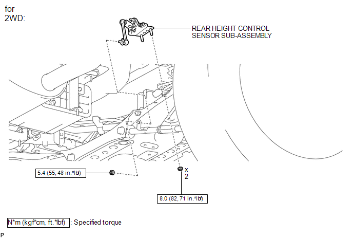
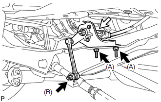
1. REMOVE REAR HEIGHT CONTROL SENSOR SUB-ASSEMBLY (for 2WD)
|
(a) Disconnect the connector. |
|
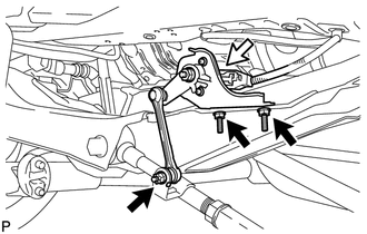
(b) Remove the 3 nuts and rear height control sensor sub-assembly.
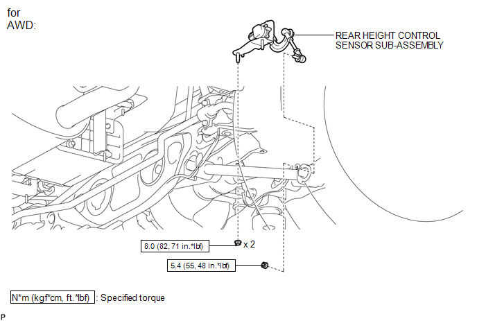
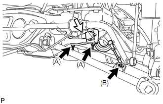
2. REMOVE REAR HEIGHT CONTROL SENSOR SUB-ASSEMBLY (for AWD)
|
(a) Disconnect the connector. |
|
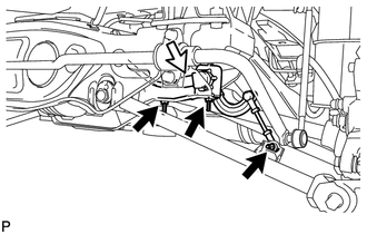
(b) Remove the 3 nuts and rear height control sensor sub-assembly.
Inspection
INSPECTION
PROCEDURE
1. INSPECT REAR HEIGHT CONTROL SENSOR SUB-ASSEMBLY RH (for 2WD)
|
(a) Connect 3 dry cell batteries (1.5 V) in series. |
|
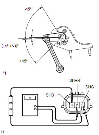
(b) Connect a positive (+) lead from the batteries to terminal 3 (SHB) and a negative (-) lead from the batteries to terminal 1 (SHG).
(c) Measure the voltage between terminals 2 (SHRR) and 1 (SHG) while slowly moving the link up and down.
Standard Voltage:
|
Tester Connection |
Condition |
Specified Condition |
|---|---|---|
|
2 (SHRR) - 1 (SHG) |
+45° (High) |
4.05 V |
|
2 (SHRR) - 1 (SHG) |
0° (normal) |
2.25 V |
|
2 (SHRR) - 1 (SHG) |
-45° (Low) |
0.45 V |
|
*1 |
Component without harness connected (Rear Height Control Sensor Sub-assembly RH) |
If the result is not as specified, replace the rear height control sensor sub-assembly RH.
2. INSPECT REAR HEIGHT CONTROL SENSOR SUB-ASSEMBLY RH (for AWD)
|
(a) Connect 3 dry cell batteries (1.5 V) in series. |
|
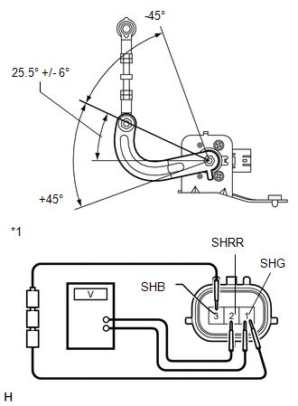
(b) Connect a positive (+) lead from the batteries to terminal 3 (SHB) and a negative (-) lead from the batteries to terminal 1 (SHG).
(c) Measure the voltage between terminals 2 (SHRR) and 1 (SHG) while slowly moving the link up and down.
Standard Voltage:
|
Tester Connection |
Condition |
Specified Condition |
|---|---|---|
|
2 (SHRR) - 1 (SHG) |
+45° (High) |
4.05 V |
|
2 (SHRR) - 1 (SHG) |
0° (normal) |
2.25 V |
|
2 (SHRR) - 1 (SHG) |
-45° (Low) |
0.45 V |
|
*1 |
Component without harness connected (Rear Height Control Sensor Sub-assembly RH) |
If the result is not as specified, replace the rear height control sensor sub-assembly RH.
Installation
INSTALLATION
PROCEDURE
1. INSTALL REAR HEIGHT CONTROL SENSOR SUB-ASSEMBLY (for 2WD)
|
(a) Install the rear height control sensor sub-assembly with the 3 nuts. Torque: Nut (A) : 8.0 N·m {82 kgf·cm, 71 in·lbf} Nut (B) : 5.4 N·m {55 kgf·cm, 48 in·lbf} |
|
(b) Connect the connector.
2. INSTALL REAR HEIGHT CONTROL SENSOR SUB-ASSEMBLY (for AWD)
|
(a) Install the rear height control sensor sub-assembly with the 3 nuts. Torque: Nut (A) : 8.0 N·m {82 kgf·cm, 71 in·lbf} Nut (B) : 5.4 N·m {55 kgf·cm, 48 in·lbf} |
|
(b) Connect the connector.
3. HEIGHT CONTROL SENSOR SIGNAL INITIALIZATION
(See page .gif) )
)
4. PREPARE VEHICLE FOR HEADLIGHT AIM ADJUSTMENT
5. PREPARE FOR HEADLIGHT AIMING
6. INSPECT HEADLIGHT AIMING
7. ADJUST HEADLIGHT AIMING
 Headlight Leveling Ecu
Components
COMPONENTS
ILLUSTRATION
Removal
REMOVAL
PROCEDURE
1. REMOVE HEADLIGHT LEVELING ECU ASSEMBLY
(a) Disconnect the connector.
...

Other materials about Toyota Venza:
Brake Override System
DESCRIPTION
When the vehicle is being driven, depressing the accelerator pedal sensor assembly
and brake pedal will activate the brake override system to restrict driving torque.
The conditions for activating the brake override system as well as the items ...
Initialization
INITIALIZATION
1. RESET BACK DOOR CLOSE POSITION
NOTICE:
Perform initialization of the power back door system (power back door ECU initialization)
if one of the following is performed:
The cable is disconnected from the negative (-) battery termin ...
Transmission Fluid Temperature Sensor "A" Circuit Low Input (P0712,P0713)
DESCRIPTION
The Automatic Transmission Fluid (ATF) temperature sensor converts the fluid
temperature into a resistance value for use by the TCM.
The TCM applies a voltage to the temperature sensor through terminal THO1 of
the TCM.
The sensor resistanc ...

0.1528