Toyota Venza: Removal
REMOVAL
PROCEDURE
1. REMOVE FRONT WHEEL LH
2. REMOVE FRONT FENDER OUTSIDE MOULDING LH
.gif)
3. REMOVE FRONT FENDER LINER LH
|
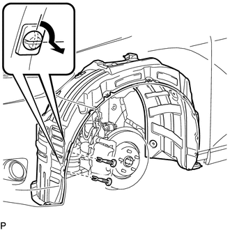
(a) Using a screwdriver, turn the pin 90 degrees and remove the 2 pin hold clips. Text in Illustration
|
|
|
(b) Remove the 5 clips <A>. Text in Illustration
|
|
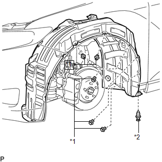
(c) Remove the clip <B>.
|
(d) Remove the bolt and 6 screws. |
|
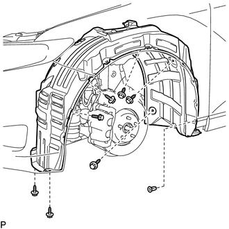
(e) Remove the grommet and front fender liner LH.
HINT:
The grommets need to be replaced with new ones because they will break when they are removed.
4. REMOVE COOL AIR INTAKE DUCT SEAL
5. REMOVE RADIATOR GRILLE
6. REMOVE LOW PITCHED HORN ASSEMBLY
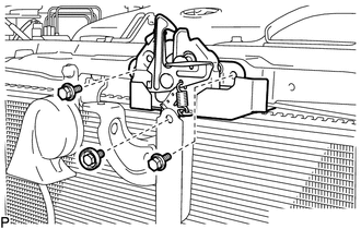
7. REMOVE HOOD LOCK ASSEMBLY (w/o Engine Hood Courtesy Switch)
|
(a) Using a screwdriver, remove the hood lock nut cap. Text in Illustration
HINT: Tape the screwdriver tip before use. |
|
|
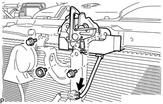
(b) Remove the 3 bolts. |
|
|
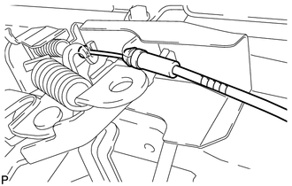
(c) Disconnect the hood lock control cable and remove the hood lock assembly. |
|
8. REMOVE HOOD LOCK ASSEMBLY (w/ Engine Hood Courtesy Switch)
|
(a) Using a screwdriver, remove the hood lock nut cap. Text in Illustration
HINT: Tape the screwdriver tip before use. |
|
|
(b) Disconnect the connector. |
|
(c) Remove the 3 bolts.
|
(d) Disconnect the hood lock control cable and remove the hood lock assembly. |
|
9. REMOVE FRONT DOOR SCUFF PLATE LH
10. REMOVE COWL SIDE TRIM SUB-ASSEMBLY LH
11. REMOVE LOWER NO. 1 INSTRUMENT PANEL FINISH PANEL
12. REMOVE HOOD LOCK CONTROL CABLE ASSEMBLY
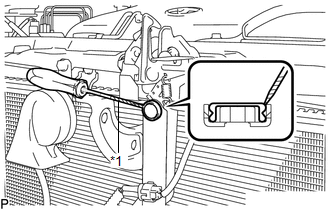
(a) Using a screwdriver, disconnect each clamp shown in the illustration.
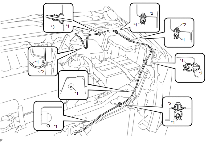 Text in Illustration
|
*1 |
Hood Lock Control Cable |
*3 |
Hood Cable Grommet |
|
*2 |
Clamp |
- |
- |
HINT:
Tape the screwdriver tip before use.
(b) Pull the hood lock control cable assembly from the engine compartment and remove it.
 Installation
INSTALLATION
PROCEDURE
1. INSTALL HOOD LOCK CONTROL CABLE ASSEMBLY
(a) Pass the hood lock control cable assembly into the engine compartment.
(b) Pass the cable through the upper radiator support. ...
 Power Back Door Closer Switch
Components
COMPONENTS
ILLUSTRATION
Removal
REMOVAL
PROCEDURE
1. REMOVE BACK DOOR PANEL TRIM ASSEMBLY
2. REMOVE POWER BACK DOOR CLOSER SWITCH ASSEMBLY
(a) Disconnect the con ...
Other materials about Toyota Venza:
Precaution
PRECAUTION
1. EXPRESSIONS OF IGNITION SWITCH
(a) The type of ignition switch used on this model differs according to the specifications
of the vehicle. The expressions listed in the table below are used in this section.
Switch Type
I ...
Inspection
INSPECTION
PROCEDURE
1. INSPECT SPIRAL CABLE
(a) Visually check for defects with the spiral cable removed from the vehicle.
(1) The defects are as follows:
Scratches on the spiral cable
Small cracks the spiral cable
Dents on the spiral cabl ...
A/C ECU Vehicle Information Reading/Writing Processor Malfunction (B15F5)
DESCRIPTION
This DTC is stored when items controlled by the air conditioning amplifier assembly
cannot be customized via the audio and visual system vehicle customization screen.
HINT:
The air conditioning amplifier assembly controls the air conditioning ...

0.1327