Toyota Venza: Differential Mount Cushion
Components
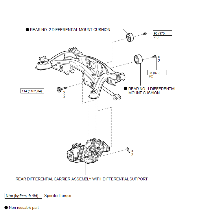
COMPONENTS
ILLUSTRATION
Installation
INSTALLATION
PROCEDURE
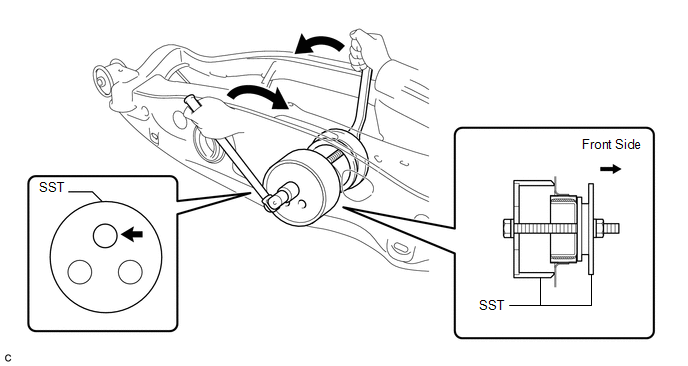
1. INSTALL REAR NO. 1 DIFFERENTIAL MOUNT CUSHION
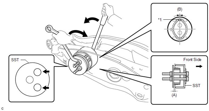
(a) Using SST, install a new rear No. 1 differential mount cushion.
 Text in Illustration
|
*1 |
Protrusion |
- |
- |
SST: 09570-24011
(A):
5.0 to 6.0 mm (0.197 to 0.236 in.)
(B):
+/- 3°
NOTICE:
- Install the rear No. 1 differential mount cushion so that the protrusion is positioned upward.
- Install the rear No. 1 differential mount cushion within +/- 3° from the center.
- Temporarily install the rear No. 1 differential mount cushion to the rear suspension member before installing SST to prevent the rear No. 1 differential mount cushion from being tilted.
- Apply grease to the threads of the SST bolts before use.
- Be sure to use SST in the correct combination.
- Do not set SST in the wrong direction.
- Make sure that SST contacts the entire rear No. 1 differential mount cushion seating surface.
- Do not slant the SST bolts.
- Tighten the 2 SST bolts equally into the 2 rear No. 1 differential mount cushion holes.
2. INSTALL REAR NO. 2 DIFFERENTIAL MOUNT CUSHION
(a) Using SST, install a new rear No. 2 differential mount cushion.
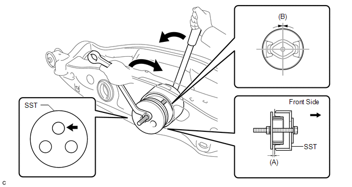
SST: 09570-24011
(A):
5.0 to 6.0 mm (0.197 to 0.236 in.)
(B):
+/- 3°
NOTICE:
- Install the rear No. 2 differential mount cushion within +/- 3° from the center.
- Temporarily install the rear No. 2 differential mount cushion to the rear suspension member before installing SST to prevent the rear No. 2 differential mount cushion from being tilted.
- Apply grease to the threads of the SST bolts before use.
- Be sure to use SST in the correct combination.
- Do not set SST in the wrong direction.
- Make sure that SST contacts the entire rear No. 2 differential mount cushion seating surface.
- Do not slant the SST bolts.
3. INSTALL REAR DIFFERENTIAL CARRIER ASSEMBLY WITH DIFFERENTIAL SUPPORT
HINT:
Refer to the procedure from Install Rear Differential Carrier Assembly with Differential
Support (See page .gif) ).
).
Removal
REMOVAL
PROCEDURE
1. REMOVE REAR DIFFERENTIAL CARRIER ASSEMBLY WITH DIFFERENTIAL SUPPORT
HINT:
Refer to the procedure up to Remove Rear Differential Carrier Assembly with Differential
Support (See page .gif) ).
).
2. REMOVE REAR NO. 1 DIFFERENTIAL MOUNT CUSHION
(a) Using SST, remove the rear No. 1 differential mount cushion.
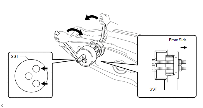
SST: 09316-12010
SST: 09570-24011
NOTICE:
- Do not bring SST into contact with the rear suspension member.
- Do not slant the SST bolts.
- Do not set SST in the wrong direction.
- Tighten the 2 SST bolts equally into the 2 rear No. 1 differential mount cushion holes.
3. REMOVE REAR NO. 2 DIFFERENTIAL MOUNT CUSHION
(a) Using SST, remove the rear No. 2 differential mount cushion.
SST: 09316-12010
SST: 09570-24011
NOTICE:
- Do not bring SST into contact with the rear suspension member.
- Do not slant the SST bolts.
- Do not set SST in the wrong direction.
 Problem Symptoms Table
PROBLEM SYMPTOMS TABLE
HINT:
Use the table below to help determine the cause of problem symptoms. If multiple
suspected areas are listed, the potential causes of the symptoms are listed in order
...
 Differential Oil
Replacement
REPLACEMENT
CAUTION / NOTICE / HINT
HINT:
Stop the vehicle on a level surface.
PROCEDURE
1. DRAIN DIFFERENTIAL OIL
(a) Using a 10 mm hexagon wrench, remove the rear dif ...
Other materials about Toyota Venza:
Disassembly
DISASSEMBLY
PROCEDURE
1. REMOVE TRANSFER AND TRANSAXLE SETTING STUD BOLT
(a) Remove the 4 transfer and transaxle setting stud bolts.
2. REMOVE NO. 2 TRANSFER CASE PLUG
(a) Remove the No. ...
Removal
REMOVAL
CAUTION / NOTICE / HINT
HINT:
Use the same procedure for the RH side and LH side.
The procedure listed below is for the LH side.
PROCEDURE
1. REMOVE REAR WHEEL
2. SEPARATE NO. 3 PARKING BRAKE CABLE ASSEMBLY
(a) Remov ...
Lost Communication with Rear Airbag Sensor LH (B1637/82,B1638/82,B1647/82,B1697/82,B1698/82)
DESCRIPTION
The side collision sensor LH circuit (to determine deployment of the front seat
side airbag assembly LH and curtain shield airbag assembly LH) is composed of the
center airbag sensor assembly, rear airbag sensor LH and side airbag sensor LH.
...

0.1764