Toyota Venza: Parts Location
PARTS LOCATION
ILLUSTRATION
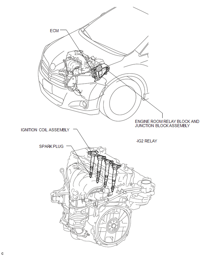
 Ignition System
...
 System Diagram
SYSTEM DIAGRAM
...
Other materials about Toyota Venza:
Fog Light Assembly
Components
COMPONENTS
ILLUSTRATION
Disassembly
DISASSEMBLY
PROCEDURE
1. REMOVE FOG LIGHT BULB
(a) Turn the fog light bulb in the direction indicated by the arrow shown
in the illustration and remove it.
NOTICE:
Do not touch th ...
Installation
INSTALLATION
PROCEDURE
1. INSTALL CAMSHAFT TIMING OIL CONTROL VALVE ASSEMBLY (for Exhaust Side)
(a) Apply a light coat of engine oil to a new O-ring, and install it
to the oil control valve.
Text in Illustration
*1
...
Inspection
INSPECTION
PROCEDURE
1. INSPECT COMPRESSOR WITH PULLEY (SOLENOID VALVE)
(a) Measure the resistance according to the value(s) in the table below.
Standard Resistance:
Tester Connection
Condition
...

0.1318