Toyota Venza: Installation
INSTALLATION
PROCEDURE
1. ADJUST COMPRESSOR OIL LEVEL
|
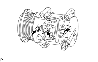
(a) When replacing the cooler compressor assembly with a new one, gradually discharge the inert gas (helium) from the service valve, and drain the following amount of oil from the vents indicated by the arrows in the illustration before installation. HINT: The drain bolt and washer can be reused. Standard: (Oil capacity inside the new compressor assembly with pulley: 130 + 15 cc (4.4 + 0.51 fl.oz.) ) - (Remaining oil amount in the removed compressor assembly with pulley) = (Oil amount to be removed from the new compressor when replacing) NOTICE:
|
|
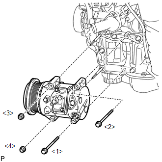
2. INSTALL COMPRESSOR ASSEMBLY WITH PULLEY
|
(a) Using an E8 "TORX" socket wrench, install the 2 stud bolts. Torque: 10 N·m {102 kgf·cm, 7 ft·lbf} |
|
.png)
|
(b) Install the the 2 bolts and 2 nuts to the compressor assembly with pulley. Torque: 25 N·m {255 kgf·cm, 18 ft·lbf} NOTICE: Tighten the bolts and nuts in the order shown in the illustration to install the compressor assembly with pulley. |
|
3. CONNECT SUCTION HOSE SUB-ASSEMBLY
(a) Remove the attached vinyl tape from the hose.
(b) Apply sufficient compressor oil to a new O-ring and the fitting surface of the compressor assembly with pulley.
Compressor oil:
ND-OIL 8 or equivalent
(c) Install the O-ring onto the suction hose sub-assembly.
NOTICE:
Keep the O-ring and O-ring fitting surfaces free from dirt or any foreign objects.
|
(d) Install the suction hose sub-assembly onto the compressor assembly with pulley with the bolt. Torque: 9.8 N·m {100 kgf·cm, 87 in·lbf} |
|
.png)
4. CONNECT COOLER REFRIGERANT DISCHARGE HOSE
(a) Remove the attached vinyl tape from the hose.
(b) Apply sufficient compressor oil to a new O-ring and the fitting surface of the compressor assembly with pulley.
Compressor oil:
ND-OIL 8 or equivalent
(c) Install the O-ring onto the discharge hose.
NOTICE:
Keep the O-ring and O-ring fitting surfaces free from dirt or any foreign objects.
|
(d) Install the cooler refrigerant discharge hose onto the compressor assembly with pulley with the bolt. Torque: 9.8 N·m {100 kgf·cm, 87 in·lbf} |
|
.png)
|
(e) Using pliers, grip the claws of the clip and slide the clip to install the No. 2 radiator hose. |
|
.png)
|
(f) Engage each clamp. |
|
.png)
(g) Connect each connector.
5. INSTALL RADIATOR ASSEMBLY
HINT:
Refer to the procedure for Install Radiator Assembly (See page
.gif) ).
).
6. INSTALL V-RIBBED BELT
7. INSTALL FRONT FENDER APRON SEAL RH
8. INSTALL FRONT FENDER LINER RH
9. INSTALL FRONT WHEEL RH
10. CONNECT CABLE TO NEGATIVE BATTERY TERMINAL
NOTICE:
When disconnecting the cable, some systems need to be initialized after the cable
is reconnected (See page ).
11. CHARGE WITH REFRIGERANT
12. WARM UP ENGINE
13. INSPECT FOR REFRIGERANT LEAK
14. INSTALL NO. 1 ENGINE UNDER COVER
 Removal
REMOVAL
PROCEDURE
1. RECOVER REFRIGERANT FROM REFRIGERATION SYSTEM
2. DISCONNECT CABLE FROM NEGATIVE BATTERY TERMINAL
NOTICE:
When disconnecting the cable, some systems need to be initialized ...

Other materials about Toyota Venza:
Data List / Active Test
DATA LIST / ACTIVE TEST
HINT:
Using the Techstream to read the Data List allows the values or states of switches,
sensors, actuators and other items to be read without removing any parts. This non-intrusive
inspection can be very useful because intermitt ...
Capacity and distribution
Cargo capacity depends on the total weight of the occupants.
(Cargo capacity) = (Total load capacity) — (Total weight of occupants) Steps
for Determining Correct Load Limit—
(1) Locate the statement “The combined weight of occupants and cargo should ...
Fuel Sender Open Detected (B1500)
DESCRIPTION
This DTC is output when the combination meter assembly detects a fuel sender
gauge malfunction via the direct line.
DTC No.
DTC Detection Condition
Trouble Area
B1500
When either of t ...

0.1512