Toyota Venza: Parts Location
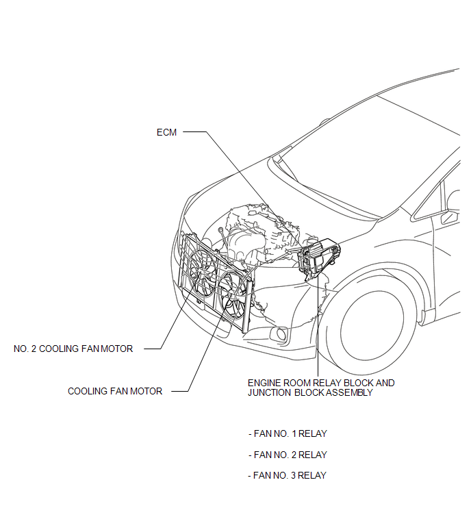
PARTS LOCATION
ILLUSTRATION
 Precaution
PRECAUTION
NOTICE:
When the ignition switch is turned off and the engine temperature is
high, the cooling fans may operate for a maximum of 6 minutes.
After turning the ignition swit ...
 System Diagram
SYSTEM DIAGRAM
...
Other materials about Toyota Venza:
Actuator Check
ACTUATOR CHECK
1. ACTUATOR CHECK
(a) Start the engine and warm it up.
(b) Perform the indicator check (See page
).
(c) Press the "Recirculation/Fresh" switch to perform the actuator check.
HINT:
Be sure to perform the actuator check after ...
MIL Circuit
DESCRIPTION
The MIL (Malfunction Indicator Lamp) is used to indicate vehicle malfunctions
detected by the ECM. By turning the ignition switch to ON, power is supplied to
the MIL circuit, and the ECM provides the circuit ground which illuminates the MIL.
...
Open in Outside Luggage Compartment Electrical Key Antenna Circuit (B27A8)
DESCRIPTION
The certification ECU (smart key ECU assembly) generates a request signal and
sends it to the outside electrical key oscillator (for rear side). To detect the
key near the driver door, the outside electrical key oscillator (for rear side)
cr ...

0.1158