Toyota Venza: Parts Location
PARTS LOCATION
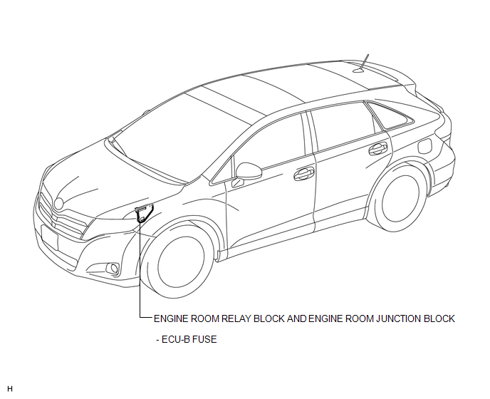
ILLUSTRATION
ILLUSTRATION
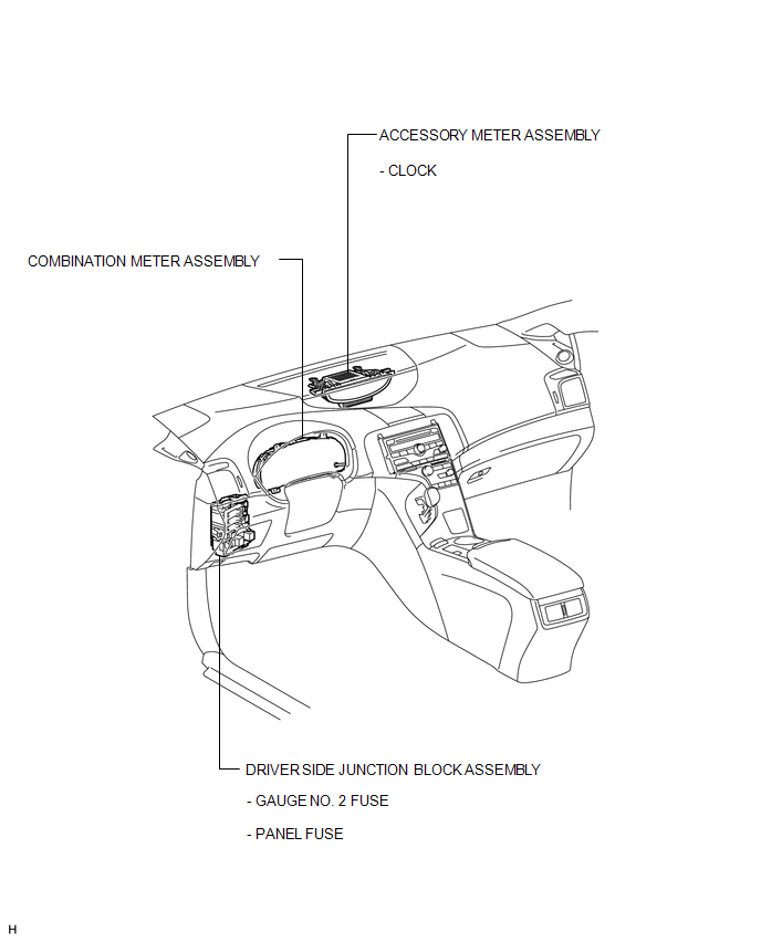
 Clock System
...
 System Diagram
SYSTEM DIAGRAM
1. CAN AND DIRECT LINE SIGNALS
2. INPUT AND OUTPUT SIGNALS OF THE ACCESSORY METER ASSEMBLY
Warning light or indicator light
Communication Signal
Re ...
Other materials about Toyota Venza:
Cooling System
On-vehicle Inspection
ON-VEHICLE INSPECTION
PROCEDURE
1. INSPECT FOR COOLANT LEAK
CAUTION:
Do not remove the radiator cap while the engine and radiator are still hot. Pressurized
hot engine coolant and steam may be released and cause serious burns.
N ...
Installation
INSTALLATION
PROCEDURE
1. INSTALL REAR ENGINE OIL SEAL
(a) Apply MP grease to the lip of a new oil seal.
NOTICE:
Do not allow foreign matter to contact the lip of the oil seal.
Do not allow MP grease to contact the dust seal.
...
Performance Decline of Brake Function (C1441)
DESCRIPTION
The skid control ECU judges brake failure conditions have occurred based on the
signal from the brake pedal load sensing switch and master cylinder pressure sensor.
NOTICE:
Do not intentionally stop the engine when driving. Even when no malfun ...

0.1181