Toyota Venza: Removal
REMOVAL
PROCEDURE
1. DISCONNECT CABLE FROM NEGATIVE BATTERY TERMINAL
CAUTION:
Wait at least 90 seconds after disconnecting the cable from the negative (-) battery terminal to disable the SRS system.
NOTICE:
When disconnecting the cable, some systems need to be initialized after the cable
is reconnected (See page .gif) ).
).
2. REMOVE FRONT SEAT ASSEMBLY LH
HINT:
Refer to the instructions for Removal of the front seat assembly.
- for Manual Seat: See page
- for Power Seat: See page
3. REMOVE UPPER CONSOLE PANEL SUB-ASSEMBLY (w/o Seat Heater System)
4. REMOVE UPPER CONSOLE PANEL SUB-ASSEMBLY (w/ Seat Heater System)
5. REMOVE NO. 2 CONSOLE BOX CARPET
6. REMOVE CONSOLE BOX ASSEMBLY
7. REMOVE AIR CONDITIONING CONTROL ASSEMBLY
8. REMOVE FRONT DOOR SCUFF PLATE LH
9. REMOVE COWL SIDE TRIM SUB-ASSEMBLY LH
10. REMOVE LOWER NO. 1 INSTRUMENT PANEL FINISH PANEL
11. REMOVE FRONT DOOR SCUFF PLATE RH
12. REMOVE COWL SIDE TRIM SUB-ASSEMBLY RH
13. REMOVE NO. 2 INSTRUMENT PANEL UNDER COVER SUB-ASSEMBLY
14. REMOVE LOWER INSTRUMENT PANEL SUB-ASSEMBLY
15. REMOVE SHIFT LEVER KNOB SUB-ASSEMBLY
16. REMOVE POSITION INDICATOR HOUSING ASSEMBLY
17. REMOVE CONSOLE BOX SUB-ASSEMBLY
18. SEPARATE PARKING BRAKE PEDAL ASSEMBLY
(a) Turn back the floor carpet.
|
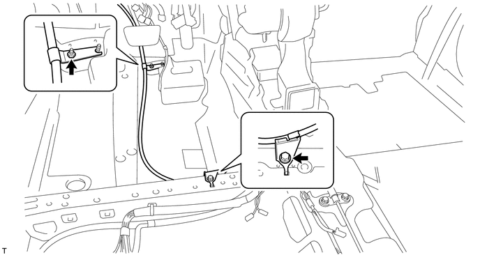
(b) Disconnect the heated oxygen sensor connector and disengage the 2 clamps (for 2GR-FE). |
|
.png)
(c) Remove the bolt and nut, and separate the No. 1 parking brake cable assembly from the body.
|
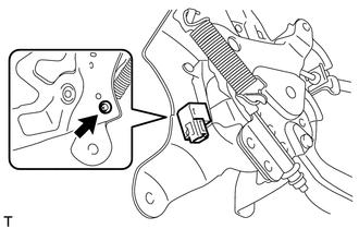
(d) Disconnect the parking brake switch connector. |
|
.png)
|
(e) Remove the 3 nuts and separate the parking brake pedal assembly from the body. |
|
.png)
19. REMOVE PARKING BRAKE SWITCH ASSEMBLY
|
(a) Remove the screw and parking brake switch assembly. |
|
 Components
COMPONENTS
ILLUSTRATION
ILLUSTRATION
ILLUSTRATION
ILLUSTRATION
...
 Inspection
INSPECTION
PROCEDURE
1. INSPECT PARKING BRAKE SWITCH ASSEMBLY
(a) Measure the resistance according to the value(s) in the table below.
Standard Resistance:
Tester ...
Other materials about Toyota Venza:
Operation Check
OPERATION CHECK
1. MALFUNCTION BUZZER
(a) Open circuit or frozen
(1) If an open circuit is detected between the ultrasonic sensors and the clearance
warning ECU assembly, if a sensor malfunction is detected or if a sensor is covered
with foreign matter, ...
Knock Sensor 1 Circuit Low Input (Bank 1 or Single Sensor) (P0327,P0328)
DESCRIPTION
Flat-type knock sensors (non-resonant type) have structures that can detect vibrations
between approximately 5 and 15 kHz.
Knock sensors are fitted onto the engine block to detect engine knocking.
The knock sensor contains a piezoelectric elem ...
Installation
INSTALLATION
PROCEDURE
1. INSTALL OUTER MIRROR SWITCH
(a) Engage the 4 claws to install the outer mirror switch.
2. INSTALL OUTER MIRROR SWITCH ASSEMBLY
(a) Engage the 2 claws to install ...

0.1515