Toyota Venza: Parts Location
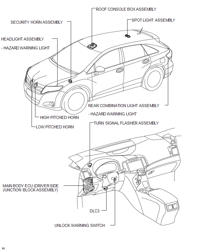
PARTS LOCATION
ILLUSTRATION
ILLUSTRATION
.png)
 Precaution
PRECAUTION
1. PRECAUTION FOR DISCONNECTING THE BATTERY CABLE
NOTICE:
When disconnecting the cable from the negative (-) battery terminal, initialize
the following systems after the terminal is re ...
 System Description
SYSTEM DESCRIPTION
1. WIRELESS DOOR LOCK CONTROL SYSTEM
The wireless door lock control system functions to lock and unlock all the doors
from a distance. The system is controlled by a door control ...
Other materials about Toyota Venza:
Reassembly
REASSEMBLY
PROCEDURE
1. INSTALL FRONT BUMPER SIDE RETAINER LH
(a) Engage the claw and install the front bumper side retainer LH.
Text in Illustration
*1
Bolt
*2
S ...
Inspection
INSPECTION
PROCEDURE
1. INSPECT REAR DOOR LOCK ASSEMBLY LH
(a) Check the operation of the door lock motor.
(1) Apply battery voltage and check the operation of the door lock motor.
OK:
Measurement Condition
...
System Description
SYSTEM DESCRIPTION
1. BRIEF DESCRIPTION
(a) The Control Area Network (CAN) is a serial data communication system for
real time application. It is a vehicle multiplex communication system which has
a high communication speed and the ability to detect malf ...

0.1318