Toyota Venza: Disassembly
DISASSEMBLY
PROCEDURE
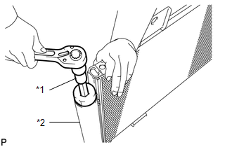
1. REMOVE COOLER DRYER
|
(a) Using a 14 mm straight hexagon wrench, remove the cap from the modulator. Text in Illustration
|
|
|
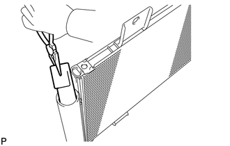
(b) Using pliers, remove the cooler dryer. |
|
 Removal
REMOVAL
PROCEDURE
1. DISCONNECT CABLE FROM NEGATIVE BATTERY TERMINAL
NOTICE:
When disconnecting the cable, some systems need to be initialized after the cable
is reconnected (See page ).
2. RE ...
 Installation
INSTALLATION
PROCEDURE
1. INSTALL COOLER CONDENSER ASSEMBLY
(a) Install the cooler condenser assembly with the 4 bolts.
Torque:
6.0 N·m {61 kgf·cm, 53 in·lbf}
HINT:
If th ...
Other materials about Toyota Venza:
Customize Parameters
CUSTOMIZE PARAMETERS
1. CUSTOMIZING FUNCTION WITH TECHSTREAM
HINT:
The items in the table below can be customized.
NOTICE:
When the customer requests a change in a function, first make sure that
the function can be customized.
Be sure to m ...
Data List / Active Test
DATA LIST / ACTIVE TEST
1. DATA LIST
HINT:
Using the Techstream to read the Data List allows the values or states of switches,
sensors, actuators and other items to be read without removing any parts. This non-intrusive
inspection can be very useful bec ...
Automatic High Beam Camera (B124C)
DESCRIPTION
The DTC is stored when the main body ECU (driver side junction block assembly)
detects malfunctions in the camera (inner rear view mirror assembly).
DTC No.
DTC Detection Condition
Trouble Area
...

0.1768