Toyota Venza: Illumination Circuit
DESCRIPTION
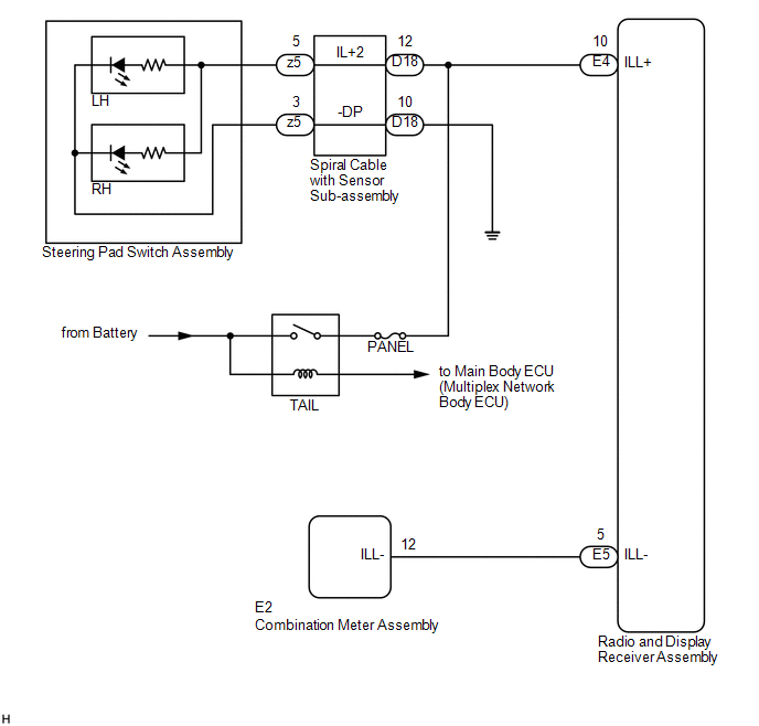
Power is supplied to the radio and display receiver assembly and steering pad switch assembly illumination when the light control switch is in the tail or head position.
WIRING DIAGRAM
CAUTION / NOTICE / HINT
NOTICE:
- The vehicle is equipped with a Supplemental Restraint System (SRS) which
includes components such as airbags. Before servicing (including removal
or installation of parts), be sure to read the precaution for Supplemental
Restraint System (See page
.gif) ).
). - Inspect the fuses for circuits related to this system before performing the following inspection procedure.
PROCEDURE
|
1. |
CHECK ILLUMINATION |
(a) Check if the illumination for the radio and display receiver assembly, steering pad switch assembly, heater control switch or others (hazard switch, transmission control switch, etc.) comes on when the light control switch is turned to the head or tail position.
|
Result |
Proceed to |
|---|---|
|
Illumination comes on for all components except steering pad switch assembly. |
A |
|
Illumination comes on for all components except radio and display receiver assembly. |
B |
|
Illumination comes on only for steering pad switch assembly. |
C |
|
No illumination comes on (radio and display receiver assembly, hazard switch, heater control switch, etc.). |
D |
| B | .gif) |
GO TO STEP 5 |
| C | |
GO TO METER / GAUGE SYSTEM |
| D | |
GO TO LIGHTING SYSTEM |
|
.gif)
|
2. |
CHECK HARNESS AND CONNECTOR (ILLUMINATION SIGNAL) |
(a) Disconnect the D18 spiral cable with sensor sub-assembly connector.
(b) Measure the voltage according to the value(s) in the table below.
Standard Voltage:
|
Tester Connection |
Condition |
Specified Condition |
|---|---|---|
|
D18-12 (IL+2) - Body ground |
Light control switch in the tail or head position |
11 to 14 V |
| NG | |
REPAIR OR REPLACE HARNESS OR CONNECTOR |
|
|
3. |
INSPECT STEERING PAD SWITCH ASSEMBLY |
(a) Remove the steering pad switch assembly (See page
).
(b) Connect a battery positive (+) lead to terminal 5 (IL+2) and a negative (-) lead to terminal 3 (-DP) of the steering pad switch assembly connector.
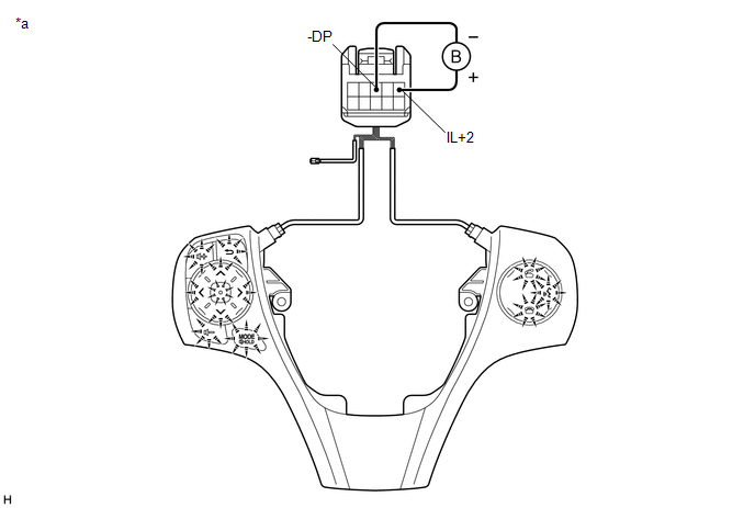 Text in Illustration
|
*a |
Component without harness connected (Steering Pad Switch Assembly) |
- |
- |
(c) Check if the illumination for the steering pad switch assembly comes on.
OK:
Illumination for the steering pad switch assembly comes on.
| NG | |
REPLACE STEERING PAD SWITCH ASSEMBLY |
|
|
4. |
INSPECT SPIRAL CABLE WITH SENSOR SUB-ASSEMBLY |
(a) Remove the spiral cable with sensor sub-assembly (See page
).
|
(b) Measure the resistance according to the value(s) in the table below. Standard Resistance:
|
|
(c) After setting the spiral cable with sensor sub-assembly to the center position, rotate the spiral cable with sensor sub-assembly 2.5 times clockwise. Then while rotating the spiral cable with sensor sub-assembly 5 times counterclockwise, measure the resistance according to the value(s) the table below.
Standard Resistance:
|
Tester Connection |
Condition |
Specified Condition |
|---|---|---|
|
z5-5 (IL+2) - D18-12 (IL+2) |
Always |
3 Ω or less |
|
z5-3 (-DP) - D18-10 (-DP) |
Always |
3 Ω or less |
NOTICE:
- The spiral cable with sensor sub-assembly is an important part of the SRS airbag system. Incorrect removal or installation of the spiral cable with sensor sub-assembly may prevent the airbag from deploying.
- As the spiral cable with sensor sub-assembly may break, do not rotate the spiral cable with sensor sub-assembly more than the specified amount.
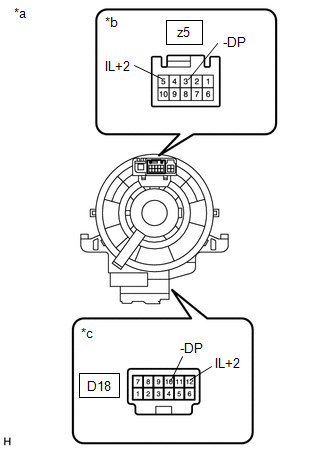
|
*a |
Component without harness connected (Spiral Cable with Sensor Sub-assembly) |
|
*b |
Steering Pad Switch Assembly Side |
|
*c |
Vehicle Side |
| OK | |
REPAIR OR REPLACE HARNESS OR CONNECTOR (SPIRAL CABLE WITH SENSOR SUB-ASSEMBLY - BODY GROUND) |
| NG | |
REPLACE SPIRAL CABLE WITH SENSOR SUB-ASSEMBLY |
|
5. |
CHECK HARNESS AND CONNECTOR (ILLUMINATION SIGNAL) |
(a) Disconnect the E4 radio and display receiver assembly connector.
(b) Measure the voltage according to the value(s) in the table below.
Standard Voltage:
|
Tester Connection |
Condition |
Specified Condition |
|---|---|---|
|
E4-10 (ILL+) - Body ground |
Light control switch in the tail or head position |
11 to 14 V |
| NG | |
REPAIR OR REPLACE HARNESS OR CONNECTOR |
|
|
6. |
CHECK HARNESS AND CONNECTOR (RADIO AND DISPLAY RECEIVER ASSEMBLY - COMBINATION METER ASSEMBLY) |
(a) Disconnect the E5 radio and display receiver assembly connector.
(b) Disconnect the E2 combination meter assembly connector.
(c) Measure the resistance according to the value(s) in the table below.
Standard Resistance:
|
Tester Connection |
Condition |
Specified Condition |
|---|---|---|
|
E5-5 (ILL-) - E2-12 (ILL-) |
Always |
Below 1 Ω |
|
E5-5 (ILL-) - Body ground |
Always |
10 kΩ or higher |
| OK | |
PROCEED TO NEXT SUSPECTED AREA SHOWN IN PROBLEM SYMPTOMS TABLE |
| NG | |
REPAIR OR REPLACE HARNESS OR CONNECTOR |
 Steering Pad Switch Circuit
DESCRIPTION
This circuit sends an operation signal from the steering pad switch assembly
to the radio and display receiver assembly.
If there is an open in the circuit, the audio system cannot be ...
 Parking Brake Switch Circuit
DESCRIPTION
This circuit is from the parking brake switch assembly to the radio and display
receiver assembly.
WIRING DIAGRAM
PROCEDURE
1.
CHECK BRAKE WARNING LIGHT
...
Other materials about Toyota Venza:
Data List / Active Test
DATA LIST / ACTIVE TEST
1. DATA LIST
HINT:
Using the Techstream to read the Data List allows the values or states of switches,
sensors, actuators and other items to be read without removing any parts. This non-intrusive
inspection can be very useful bec ...
Operation Check
OPERATION CHECK
1. INSPECT ILLUMINATED ENTRY SYSTEM OPERATION
NOTICE:
Perform this inspection with the customize parameters at the initial setting.
HINT:
The interior light control illuminates the lights below.
Transponder Key Amplifier*1
Roof ...
Dtc Check / Clear
DTC CHECK / CLEAR
1. CHECK DTC
(a) Turn the ignition switch off.
(b) Connect the Techstream to the DLC3.
(c) Turn the ignition switch to ON.
(d) Turn the Techstream on.
(e) Read the DTCs following the display on the Techstream. Enter the following
menu ...

0.1303