Toyota Venza: Taillight Relay Circuit
DESCRIPTION
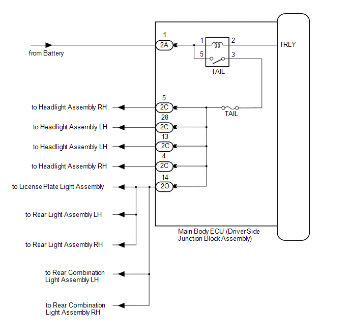
The main body ECU (driver side junction block assembly) controls the operation of the TAIL relay.
WIRING DIAGRAM
CAUTION / NOTICE / HINT
NOTICE:
Inspect the fuses for circuits related to this system before performing the following inspection procedure.
PROCEDURE
|
1. |
PERFORM ACTIVE TEST USING TECHSTREAM |
(a) Connect the Techstream to the DLC3.
(b) Turn the ignition switch to ON.
(c) Turn the Techstream on.
(d) Enter the following menus: Body Electrical / Main Body / Active Test.
(e) Check that the relay operates.
Main Body|
Tester Display |
Test Part |
Control Range |
Diagnostic Note |
|---|---|---|---|
|
Taillight Relay |
Taillight relay |
ON/OFF |
- |
OK:
Taillight relay operates. (Taillights illuminate.)
| OK | .gif) |
PROCEED TO NEXT SUSPECTED AREA SHOWN IN PROBLEM SYMPTOMS TABLE |
|
.gif)
|
2. |
INSPECT TAILLIGHT RELAY (TAIL) |
|
(a) Remove the taillight relay from the main body ECU (driver side junction block assembly). |
|
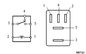
(b) Measure the resistance according to the value(s) in the table below.
Standard Resistance:
|
Tester Connection |
Condition |
Specified Condition |
|---|---|---|
|
3 - 5 |
Voltage is not applied between terminals 1 and 2 |
10 kΩ or higher |
|
Apply the battery voltage between terminals 1 and 2 |
Below 1 Ω |
|
|
3 - 4 |
Voltage is not applied between terminals 1 and 2 |
Below 1 Ω |
|
Apply the battery voltage between terminals 1 and 2 |
10 kΩ or higher |
| NG | |
REPLACE TAILLIGHT RELAY |
|
|
3. |
CHECK HARNESS AND CONNECTOR (BATTERY - MAIN BODY ECU (DRIVER SIDE JUNCTION BLOCK ASSEMBLY) |
|
(a) Disconnect the 2A main body ECU (driver side junction block assembly) connector. |
|
(b) Measure the voltage according to the value(s) in the table below.
Standard Voltage:
|
Tester Connection |
Condition |
Specified Condition |
|---|---|---|
|
2A-1 - Body ground |
Always |
11 to 14 V |
|
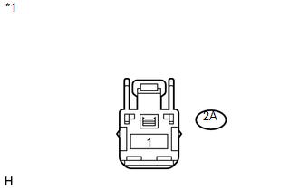
*1 |
Front view of wire harness connector (to Main Body ECU (Driver Side Junction Block Assembly)) |
| OK | |
REPLACE MAIN BODY ECU (DRIVER SIDE JUNCTION BLOCK ASSEMBLY) |
| NG | |
REPAIR OR REPLACE HARNESS OR CONNECTOR |
 Parking Brake Switch Circuit
DESCRIPTION
The main body ECU (driver side junction block assembly) detects the condition
of the parking brake switch.
WIRING DIAGRAM
PROCEDURE
1.
READ VALUE USING TECHS ...
 Headlight Beam Level Control Actuator Circuit
DESCRIPTION
The headlight leveling ECU assembly actuates the headlight leveling motor according
to vehicle conditions.
WIRING DIAGRAM
PROCEDURE
1.
READ VALUE USING TECHS ...
Other materials about Toyota Venza:
Precaution
PRECAUTION
1. PRECAUTION FOR DISCONNECTING CABLE FROM NEGATIVE BATTERY TERMINAL
NOTICE:
When disconnecting the cable from the negative (-) battery terminal, initialize
the following system after the cable is reconnected.
System Name
...
Transfer Case Front Oil Seal(when Not Using The Engine Support Bridge)
Components
COMPONENTS
ILLUSTRATION
Replacement
REPLACEMENT
PROCEDURE
1. REMOVE TRANSFER ASSEMBLY
(See page ).
2. REMOVE TRANSFER CASE FRONT OIL SEAL
(a) Using SST, remove the transfer case front oil seal from the transfer
case.
...
Diagnosis System
DIAGNOSIS SYSTEM
1. DESCRIPTION
(a) Air conditioning system data and the Diagnostic Trouble Codes (DTCs) can
be read through the Data Link Connector 3 (DLC3) of the vehicle. When the system
seems to be malfunctioning, use the Techstream to check for malf ...

0.155