Toyota Venza: One or more Power Seat Motors do not Operate
DESCRIPTION
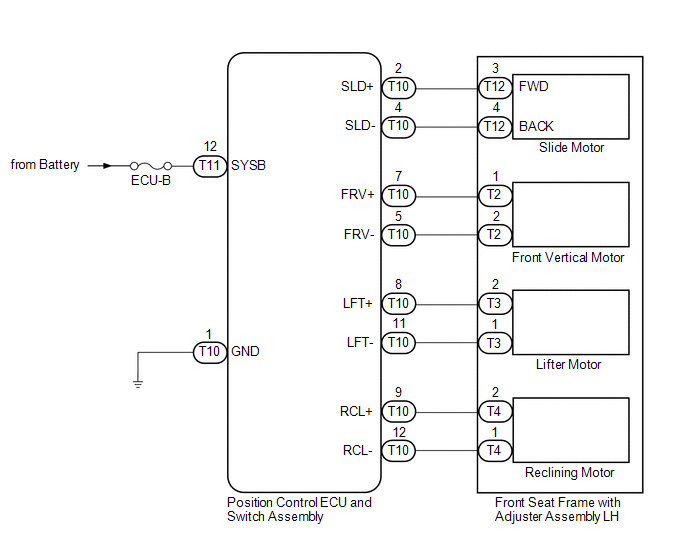
Signals are input into the position control ECU and switch assembly. The built-in ECU manages the signals received from the position control ECU and switch assembly, and operates each motor. If the position control ECU and switch assembly receives more than 2 motor operation signals, the motor is stopped. Manual operation is restarted after the position control ECU and switch assembly receives 1 signal only.
WIRING DIAGRAM
CAUTION / NOTICE / HINT
NOTICE:
Inspect the fuses for circuits related to this system before performing the following inspection procedure.
PROCEDURE
|
1. |
READ VALUE USING TECHSTREAM |
(a) Connect the Techstream to the DLC3.
(b) Turn the ignition switch to ON.
(c) Turn the Techstream on.
(d) Enter the following menus: Body Electrical / Driver Seat / Data List.
(e) Read the Data List according to the display on the Techstream.
Driver Seat|
Tester Display |
Measurement Item/Range |
Normal Condition |
Diagnostic Note |
|---|---|---|---|
|
Reclining Rear |
Reclining switch signal (Rearward) / ON or OFF |
ON: Reclining switch (Rearward) on OFF: Reclining switch (Rearward) off |
- |
|
Reclining Front |
Reclining switch signal (Forward) / ON or OFF |
ON: Reclining switch (Forward) on OFF: Reclining switch (Forward) off |
- |
|
Front Vertical Down |
Front vertical switch signal (Downward) / ON or OFF |
ON: Front vertical switch (Downward) on OFF: Front vertical switch (Downward) off |
- |
|
Front Vertical Up |
Front vertical switch signal (Upward) / ON or OFF |
ON: Front vertical switch (Upward) on OFF: Front vertical switch (Upward) off |
- |
|
Lifter Switch Down |
Lifter switch signal (Downward) / ON or OFF |
ON: Lifter switch (Downward) on OFF: Lifter switch (Downward) off |
- |
|
Lifter Switch Up |
Lifter switch signal (Upward) / ON or OFF |
ON: Lifter switch (Upward) on OFF: Lifter switch (Upward) off |
- |
|
Slide Rear |
Sliding switch signal (Rearward) / ON or OFF |
ON: Sliding switch (Rearward) on OFF: Sliding switch (Rearward) off |
- |
|
Slide Front |
Sliding switch signal (Forward) / ON or OFF |
ON: Sliding switch (Forward) on OFF: Sliding switch (Forward) off |
- |
OK:
ON or OFF is displayed on the Techstream according to the table above.
| NG | .gif) |
GO TO STEP 5 |
|
.gif)
|
2. |
PERFORM ACTIVE TEST USING TECHSTREAM |
(a) Enter the following menus: Body Electrical / Driver Seat / Active Test.
(b) Perform the Active Test according to the display on the Techstream.
Driver Seat|
Tester Display |
Test Part |
Control Range |
Diagnostic Note |
|---|---|---|---|
|
Seat Reclining |
Seat reclining operation |
OFF/Front/Rear |
- |
|
Front Vertical Operation |
Seat front vertical operation |
OFF/Up/Down |
- |
|
Lifter Operation |
Seat lifter operation |
OFF/Up/Down |
- |
|
Seat Slide Operation |
Seat sliding operation |
OFF/Front/Rear |
- |
OK:
The power seat motors operate normally.
| OK | |
REPLACE POSITION CONTROL ECU AND SWITCH ASSEMBLY |
|
|
3. |
INSPECT FRONT SEAT FRAME WITH ADJUSTER ASSEMBLY LH |
|
(a) Remove the front seat frame with adjuster assembly LH (See page
|
|
.gif) ).
)..png)
(b) Check operation of the slide motor.
(1) Check if the seat moves smoothly when the battery is connected to the slide motor connector terminals.
OK:
|
Condition |
Specified Condition |
|---|---|
|
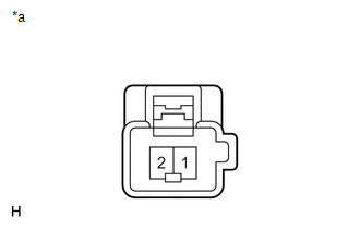
Battery positive (+) → Terminal 3 Battery negative (-) → Terminal 4 |
Forward |
|
Battery positive (+) → Terminal 4 Battery negative (-) → Terminal 3 |
Rearward |
|
*a |
Component without harness connected (Slide Motor (Front Seat Frame with Adjuster Assembly LH)) |
|
(c) Check operation of the front vertical motor. (1) Check if the seat moves smoothly when the battery is connected to the front vertical motor connector terminals. OK:
|
|
|
(d) Check operation of the lifter motor. (1) Check if the seat moves smoothly when the battery is connected to the lifter motor connector terminals. OK:
|
|
|
(e) Check operation of the reclining motor. (1) Check if the seat moves smoothly when the battery is connected to the reclining motor connector terminals. OK:
|
|
| NG | |
REPLACE FRONT SEAT FRAME WITH ADJUSTER ASSEMBLY LH |
|
|
4. |
CHECK HARNESS AND CONNECTOR (POSITION CONTROL ECU AND SWITCH ASSEMBLY - POWER SEAT MOTOR) |
(a) Disconnect the T10 the position control ECU and switch assembly connector.
(b) Measure the resistance according to the value(s) in the table below.
Standard Resistance:
|
Tester Connection |
Condition |
Specified Condition |
|---|---|---|
|
T10-2 (SLD+) - T12-3 (FWD) |
Always |
Below 1 Ω |
|
T10-4 (SLD-) - T12-4 (BACK) |
Always |
Below 1 Ω |
|
T10-5 (FRV-) - T2-2 |
Always |
Below 1 Ω |
|
T10-7 (FRV+) - T2-1 |
Always |
Below 1 Ω |
|
T10-8 (LFT+) - T3-2 |
Always |
Below 1 Ω |
|
T10-11 (LFT-) - T3-1 |
Always |
Below 1 Ω |
|
T10-9 (RCL+) - T4-2 |
Always |
Below 1 Ω |
|
T10-12 (RCL-) - T4-1 |
Always |
Below 1 Ω |
|
T10-2 (SLD+) - Body ground |
Always |
10 kΩ or higher |
|
T10-4 (SLD-) - Body ground |
Always |
10 kΩ or higher |
|
T10-5 (FRV-) - Body ground |
Always |
10 kΩ or higher |
|
T10-7 (FRV+) - Body ground |
Always |
10 kΩ or higher |
|
T10-8 (LFT+) - Body ground |
Always |
10 kΩ or higher |
|
T10-11 (LFT-) - Body ground |
Always |
10 kΩ or higher |
|
T10-9 (RCL+) - Body ground |
Always |
10 kΩ or higher |
|
T10-12 (RCL-) - Body ground |
Always |
10 kΩ or higher |
| OK | |
REPLACE POSITION CONTROL ECU AND SWITCH ASSEMBLY |
| NG | |
REPAIR OR REPLACE HARNESS OR CONNECTOR |
|
5. |
CHECK HARNESS AND CONNECTOR (BATTERY - POSITION CONTROL ECU AND SWITCH ASSEMBLY - BODY GROUND) |
(a) Disconnect the T11 the position control ECU and switch assembly connector.
(b) Measure the voltage and resistance according to the value(s) in the table below.
Standard Voltage:
|
Tester Connection |
Condition |
Specified Condition |
|---|---|---|
|
T11-12 (SYSB) - Body ground |
Always |
11 to 14 V |
Standard Resistance:
|
Tester Connection |
Condition |
Specified Condition |
|---|---|---|
|
T10-1 (GND) - Body ground |
Always |
Below 1 Ω |
| OK | |
REPLACE POSITION CONTROL ECU AND SWITCH ASSEMBLY |
| NG | |
REPAIR OR REPLACE HARNESS OR CONNECTOR |
 Front Power Seat does not Operate with Front Power Seat Switch
DESCRIPTION
Signals are input into the position control ECU and switch assembly. The built-in
ECU manages the signals received from the position control ECU and switch assembly,
and operates each ...
 Power Seat Position is not Memorized
DESCRIPTION
The main body ECU (driver side junction block assembly) receives seat memory
switch signals from the outer mirror control ECU assembly LH via CAN communication.
If the seat memory SET ...
Other materials about Toyota Venza:
Removal
REMOVAL
PROCEDURE
1. REMOVE BACK DOOR PANEL TRIM ASSEMBLY
2. REMOVE REAR WIPER ARM HEAD CAP
3. REMOVE REAR WIPER ARM AND BLADE ASSEMBLY
4. REMOVE REAR WIPER MOTOR GROMMET
5. REMOVE REAR WIPER MOTOR AND BRACKET ASSEMBLY
6. REMOVE REAR LIGH ...
Installation
INSTALLATION
PROCEDURE
1. INSTALL REAR SEAT INNER BELT ASSEMBLY RH
(a) Install the rear seat inner belt assembly RH with the bolt.
Torque:
42 N·m {428 kgf·cm, 31 ft·lbf}
2. INSTALL REAR SE ...
Selecting trailer ball
Use the correct trailer ball for your application.
1. Trailer ball load rating
Matches or exceeds the gross trailer weight rating of the trailer.
2. Ball diameter
Matches the size of the trailer coupler. Most couplers are stamped with the required
trai ...

0.1597