Toyota Venza: Removal
REMOVAL
PROCEDURE
1. REMOVE FRONT SEAT HEADREST ASSEMBLY
2. REMOVE FRONT SEAT REAR OUTER TRACK COVER
.gif)
3. REMOVE FRONT SEAT REAR INNER TRACK COVER
4. REMOVE FRONT SEAT ASSEMBLY
5. REMOVE SLIDE AND VERTICAL POWER SEAT SWITCH KNOB
6. REMOVE RECLINING POWER SEAT SWITCH KNOB
7. REMOVE FRONT SEAT CUSHION SHIELD ASSEMBLY
8. REMOVE POWER SEAT SWITCH
9. REMOVE FRONT SEAT INNER BELT ASSEMBLY
10. REMOVE FRONT INNER SEAT CUSHION SHIELD
11. REMOVE SEPARATE TYPE FRONT SEAT CUSHION COVER WITH PAD
12. REMOVE FRONT SEATBACK BOARD SUB-ASSEMBLY
13. REMOVE SEPARATE TYPE FRONT SEATBACK COVER WITH PAD
14. REMOVE LUMBAR SUPPORT ADJUSTER ASSEMBLY
|
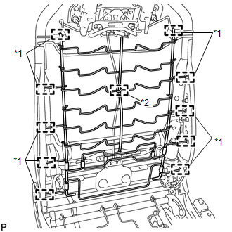
(a) Disengage the 8 guides and clamp and remove the front seatback spring sub-assembly. Text in Illustration
|
|
(b) Disconnect the connector.
|
(c) Disengage the 2 screws and guide, and remove the lumbar support adjuster assembly. |
|
.png)
|
(d) Remove the bush. |
|
.png)
 Inspection
INSPECTION
PROCEDURE
1. INSPECT LUMBAR SUPPORT ADJUSTER ASSEMBLY
(a) Check operation of the lumbar support adjuster.
(1) Check if the lumbar support adjuster moves smoothly when the battery is c ...
 Installation
INSTALLATION
PROCEDURE
1. INSTALL LUMBAR SUPPORT ADJUSTER ASSEMBLY
(a) Install the bush.
(b) Install the lumbar support adjuste ...
Other materials about Toyota Venza:
Low Power Supply Voltage (C1241/94)
DESCRIPTION
If a malfunction in the power source circuit occurs, or a malfunction in communication
with the skid control ECU or in a speed sensor occurs, the AWD control ECU will
prohibit operations by the fail-safe function.
DTC No.
...
Precaution
PRECAUTION
1. PRECAUTION FOR DISCONNECTING THE BATTERY CABLE
NOTICE:
When disconnecting the cable from the negative (-) battery terminal, initialize
the following systems after the terminal is reconnected.
System Name
See Procedure
...
Installation
INSTALLATION
PROCEDURE
1. INSTALL CHECK VALVE GROMMET
(a) Install a new check valve grommet to the brake booster assembly.
2. INSTALL BRAKE VACUUM CHECK VALVE ASSEMBLY
(a) Install the brake vacuum check valve assembly to the brake booster assembly.
3. IN ...

0.1154