Toyota Venza: Power Seat Position is not Memorized
DESCRIPTION
The main body ECU (driver side junction block assembly) receives seat memory switch signals from the outer mirror control ECU assembly LH via CAN communication. If the seat memory SET switch is being pressed when one of the M1 or M2 switches is pressed, or if one of the M1 or M2 switches is pressed within 3 seconds of pressing the seat memory SET switch, the main body ECU (driver side junction block assembly) sends a memory request signal to the position control ECU and switch assembly. After receiving the request signal, the position control ECU and switch assembly memorizes the location data of each motor.
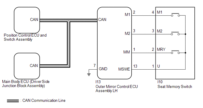
WIRING DIAGRAM
CAUTION / NOTICE / HINT
NOTICE:
- The seat position will not be recorded if the SET switch and 2 of the seat memory switches are pressed simultaneously.
- If a memorizing operation has failed, release all switches. The seat memory function does not operate unless the switches are released.
- The front power seat control system (w/ Memory) uses the CAN communication
system. First, confirm that there is no malfunction in the communication
system by checking communication function of the CAN communication system.
Refer to the How to Proceed with Troubleshooting procedure (See page
.gif) ).
).
PROCEDURE
|
1. |
CHECK FRONT POWER SEAT CONTROL SYSTEM |
(a) Check that each function of the power seat operates normally by using the
position control ECU and switch assembly (See page
).
OK:
Each function of the power seat operates normally using the position control ECU and switch assembly.
| NG | .gif) |
GO TO PROBLEM SYMPTOMS TABLE |
|
.gif)
|
2. |
READ VALUE USING TECHSTREAM (SEAT MEMORY SWITCH) |
(a) Connect the Techstream to the DLC3.
(b) Turn the ignition switch to ON.
(c) Turn the Techstream on.
(d) Enter the following menus: Body Electrical / Mirror L / Data List
(e) Read the Data List according to the display on the Techstream.
Mirror L|
Tester Display |
Measurement Item/Range |
Normal Condition |
Diagnostic Note |
|---|---|---|---|
|
Seat Memory Switch1 |
M1 switch / ON or OFF |
ON: M1 switch on OFF: M1 switch off |
- |
|
Seat Memory Switch2 |
M2 switch / ON or OFF |
ON: M2 switch on OFF: M2 switch off |
- |
|
Seat Memory Set SW |
SET switch / ON or OFF |
ON: SET switch on OFF: SET switch off |
- |
OK:
ON or OFF is displayed on the Techstream according to the table above.
| NG | |
GO TO STEP 8 |
|
|
3. |
PERFORM ACTIVE TEST USING TECHSTREAM (BUZZER) |
(a) Connect the Techstream to the DLC3.
(b) Turn the ignition switch to ON.
(c) Turn the Techstream on.
(d) Enter the following menus: Body Electrical / Driver Seat / Data List.
(e) Read the Data List according to the display on the Techstream.
Driver Seat|
Tester Display |
Test Part |
Control Range |
Diagnostic Note |
|---|---|---|---|
|
Buzzer |
Buzzer operation |
OFF/ON |
- |
OK:
Buzzer sounds normally.
| NG | |
REPLACE POSITION CONTROL ECU AND SWITCH ASSEMBLY |
|
|
4. |
REPLACE OUTER MIRROR CONTROL ECU ASSEMBLY LH |
(a) Replace the outer mirror control ECU assembly LH (See page
).
|
|
5. |
CHECK SEAT POSITION MEMORY FUNCTION |
(a) Store a seat position in memory and check that the buzzer sounds to indicate
that a position has been stored (See page ).
NOTICE:
- The seat position will not be recorded if the SET switch and 2 of the seat memory switches are pressed simultaneously.
- If a memorizing operation has failed, release all switches. The seat memory function does not operate unless the switches are released.
OK:
Seat position memory function operates normally.
| OK | |
END (OUTER MIRROR CONTROL ECU ASSEMBLY LH WAS DEFECTIVE) |
|
|
6. |
REPLACE POSITION CONTROL ECU AND SWITCH ASSEMBLY |
(a) Replace the position control ECU and switch assembly (See page
).
|
|
7. |
CHECK SEAT POSITION MEMORY FUNCTION |
(a) Store a seat position in memory and check that the buzzer sounds to indicate
that a position has been stored (See page ).
NOTICE:
- The seat position will not be recorded if the SET switch and 2 of the seat memory switches are pressed simultaneously.
- If a memorizing operation has failed, release all switches. The seat memory function does not operate unless the switches are released.
OK:
Seat position memory function operates normally.
| OK | |
END (POSITION CONTROL ECU AND SWITCH ASSEMBLY WAS DEFECTIVE) |
| NG | |
REPLACE MAIN BODY ECU (DRIVER SIDE JUNCTION BLOCK ASSEMBLY) |
|
8. |
INSPECT SEAT MEMORY SWITCH |
|
(a) Remove the seat memory switch (See page
|
|
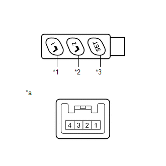
(b) Measure the resistance according to the value(s) in the table below.
Standard Resistance:
|
Tester Connection |
Condition |
Specified Condition |
|---|---|---|
|
1 - 2 |
SET switch is pressed |
Below 1 Ω |
|
SET switch is not pressed |
10 kΩ or higher |
|
|
1 - 4 |
M1 switch is pressed |
Below 1 Ω |
|
M1 switch is not pressed |
10 kΩ or higher |
|
|
1 - 3 |
M2 switch is pressed |
Below 1 Ω |
|
M2 switch is not pressed |
10 kΩ or higher |
|
*1 |
M1 Switch |
|
*2 |
M2 Switch |
|
*3 |
SET Switch |
|
*a |
Component without harness connected (Seat Memory Switch) |
| NG | |
REPLACE SEAT MEMORY SWITCH |
|
|
9. |
CHECK HARNESS AND CONNECTOR (OUTER MIRROR CONTROL ECU ASSEMBLY LH - SEAT MEMORY SWITCH) |
(a) Disconnect the I13 outer mirror control ECU assembly LH connector.
(b) Measure the resistance according to the value(s) in the table below.
Standard Resistance:
|
Tester Connection |
Condition |
Specified Condition |
|---|---|---|
|
I10-2 (MRY) - I13-1 (MM) |
Always |
Below 1 Ω |
|
I10-4 (M1) - I13-2 (M1) |
Always |
Below 1 Ω |
|
I10-3 (M2) - I13-3 (M2) |
Always |
Below 1 Ω |
|
I10-1 (U) - I13-13 (MSWE) |
Always |
Below 1 Ω |
|
I13-7 (GND) - Body ground |
Always |
Below 1 Ω |
|
I13-1 (MM) - Body ground |
Always |
10 kΩ or higher |
|
I13-2 (M1) - Body ground |
Always |
10 kΩ or higher |
|
I13-3 (M2) - Body ground |
Always |
10 kΩ or higher |
|
I13-13 (MSWE) - Body ground |
Always |
10 kΩ or higher |
| OK | |
REPLACE OUTER MIRROR CONTROL ECU ASSEMBLY LH |
| NG | |
REPAIR OR REPLACE HARNESS OR CONNECTOR |
 One or more Power Seat Motors do not Operate
DESCRIPTION
Signals are input into the position control ECU and switch assembly. The built-in
ECU manages the signals received from the position control ECU and switch assembly,
and operates each ...
 Power Seat does not Return to Memorized Position
DESCRIPTION
When either the M1 or M2 switch is pressed, the outer mirror control ECU assembly
LH sends a switch signal to the main body ECU (driver side junction block assembly)
via CAN communica ...
Other materials about Toyota Venza:
Seat Belt Buckle Switch LH Circuit Malfunction (B1656/38)
DESCRIPTION
The seat belt buckle switch LH circuit consists of the center airbag sensor assembly
and front seat inner belt assembly LH.
DTC B1656/38 is stored when a malfunction is detected in the seat belt buckle
switch LH circuit.
DTC No.
...
System Diagram
SYSTEM DIAGRAM
Communication Table
Sender
Receiver
Signal
Line
ECM
Combination Meter ECU
CRUISE main indicator operation signal
SET indicator operation sig ...
System Description
SYSTEM DESCRIPTION
1. GENERAL
The windshield deicer system's thin heater wires are attached to the inside of
the front window and deice the window surface quickly. The indicator light illuminates
while the system is operating. The system automaticall ...

0.1385