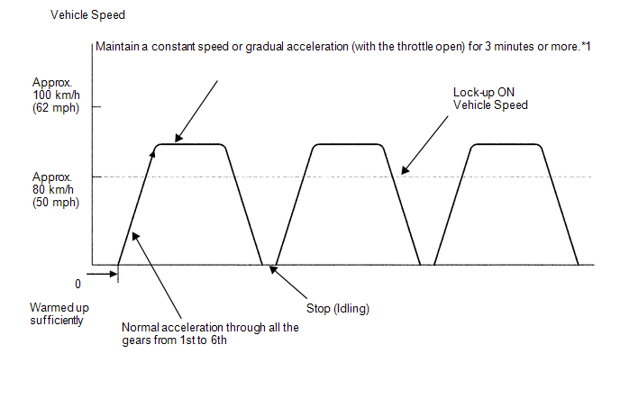
Toyota Venza: Monitor Drive Pattern
MONITOR DRIVE PATTERN
1. TEST MONITOR DRIVE PATTERN FOR ECT
CAUTION:
Perform this drive pattern on a level surface and strictly observe the posted speed limits and traffic laws while driving.
HINT:
Performing this drive pattern is one method to simulate the TCM (ECT) malfunction detection conditions.
Some DTCs may not be detected through ordinary, everyday driving. Also, DTCs may not be detected through this drive pattern.
(a) Preparation for driving
(1) Warm up the engine sufficiently (engine coolant temperature is 60°C (140°F) or higher).
(2) Drive the vehicle when the atmospheric temperature is -10°C (14°F) or higher.
Some malfunctions are not detected when the atmospheric temperature is less than -10°C (14°F).
(b) Drive pattern
(1) Drive the vehicle through all the gears.
Stop → 1st → 2nd → 3rd → 4th → 5th → 6th → 6th (lock-up ON).
(2) Confirm engine braking using the S position. While driving with S6 range selected and 6th gear operating with lock-up on, move the shift lever toward "-" to downshift from 6 to 5, 5 to 4, 4 to 3, 3 to 2, 2 to 1.
(3) Repeat the above drive pattern three times or more.
NOTICE:
- When using the Techstream, the monitor status can be checked in the
Data List (See page
.gif) ).
). - In the event that the drive pattern must be interrupted (due to traffic conditions or other factors), the drive pattern can be resumed and, in most cases, the monitor can be completed.
HINT:
*1: Drive the vehicle at a speed in top gear that will cause lock-up to engage. The vehicle can be driven at a speed lower than that in the above diagram under the lock-up condition.
NOTICE:
It is necessary to drive the vehicle for approximately 30 minutes to detect DTC P0711 (ATF temperature sensor malfunction).
 Initialization
INITIALIZATION
1. RESET TRANSAXLE COMPENSATION CODE
NOTICE:
If the following parts have been replaced, initialize the TCM and perform
the following "Reset Memory" and "Pe ...
 Problem Symptoms Table
PROBLEM SYMPTOMS TABLE
HINT:
Use the table below to help determine the cause of problem symptoms.
If multiple suspected areas are listed, the potential causes of the symptoms
are lis ...
Other materials about Toyota Venza:
Vehicle Speed Signal Error (Test Mode DTC) (C2191/91)
DESCRIPTION
The tire pressure warning ECU receives a vehicle speed signal from the combination
meter. This DTC is stored upon entering signal check mode (test mode), and cleared
when a vehicle speed signal of 20 km/h (12 mph) is detected for 3 seconds or ...
Parking Brake Switch Circuit
DESCRIPTION
The main body ECU (driver side junction block assembly) detects the condition
of the parking brake switch.
WIRING DIAGRAM
PROCEDURE
1.
READ VALUE USING TECHSTREAM
(a) Connect the Techstream to the DLC3.
(b) ...
Back door
The back door can be opened using the back door opener. The back door can
be locked and unlocked using the entry function (vehicles with smart key system),
wireless remote control or door lock switch.
In addition, the power back door (if equipped) can be ...

0.175