Toyota Venza: Malfunction in Deceleration Sensor (C0365/28,C1234/34,C1245/32,C1245/45)
DESCRIPTION
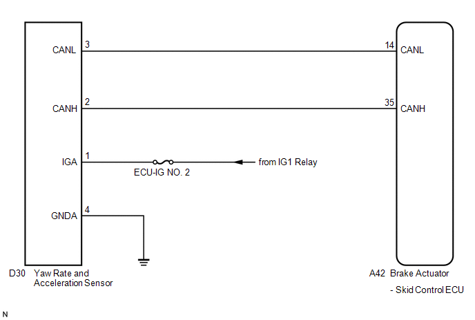
The skid control ECU receives signals from the yaw rate and acceleration sensor via the CAN communication system.
The yaw rate sensor has a built-in acceleration sensor.
If there is trouble in the bus lines between the yaw rate and acceleration sensor and the CAN communication system, DTC U0123/62 (Lost Communication with Yaw Rate Sensor Module) is output.
|
DTC Code |
DTC Detection Condition |
Trouble Area |
|---|---|---|
|
C0365/28 |
Any of the following is detected:
|
|
|
C1234/34 |
Sensor malfunction signal is received from the yaw rate sensor. |
|
|
C1245/32*1 |
Any of the following is detected:
|
|
|
C1245/45*2 |
Any of the following is detected:
|
|
*1: for 2WD
*2: for AWD
WIRING DIAGRAM
CAUTION / NOTICE / HINT
HINT:
When U0123/62 and/or U0126/63 is output together with C0365/28, C1234/34, C1245/32
and/or C1245/45 inspect and repair the trouble areas indicated by U0123/62 and/or
U0126/63 first (See page .gif) ).
).
PROCEDURE
|
1. |
CHECK DTC |
(a) Clear the DTCs (See page ).
(b) Start the engine.
(c) At a speed of 30 km/h (18 mph) or more, drive the vehicle, turn the steering wheel, and decelerate (depress the brake pedal) the vehicle.
(d) Turn the ignition switch to ON again and check that no CAN communication
system DTC is output (See page ).
|
Result |
Proceed to |
|---|---|
|
CAN communication system DTC is not output |
A |
|
CAN communication system DTC is output |
B |
| B | .gif) |
INSPECT CAN COMMUNICATION SYSTEM |
|
.gif)
|
2. |
CHECK YAW RATE AND ACCELERATION SENSOR INSTALLATION |
(a) Turn the ignition switch off.
(b) Check that the yaw rate and acceleration sensor has been installed properly
(See page ).
OK:
The sensor should be tightened to the specified torque.
The sensor should not be tilted.
| NG | |
INSTALL YAW RATE AND ACCELERATION SENSOR CORRECTLY |
|
|
3. |
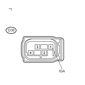
INSPECT YAW RATE AND ACCELERATION SENSOR (IGA TERMINAL) |
|
(a) Make sure that there is no looseness at the locking part and the connecting part of the connector. |
|
(b) Disconnect the yaw rate and acceleration sensor connector.
(c) Turn the ignition switch to ON.
(d) Measure the voltage according to the value(s) in the table below.
Standard Voltage:
|
Tester Connection |
Switch Condition |
Specified Condition |
|---|---|---|
|
D30-1 (IGA) - Body ground |
Ignition switch ON |
11 to 14 V |
|
*1 |
Front view of wire harness connector (to Yaw Rate and Acceleration Sensor) |
| NG | |
REPAIR OR REPLACE HARNESS OR CONNECTOR (IGA CIRCUIT) |
|
|
4. |
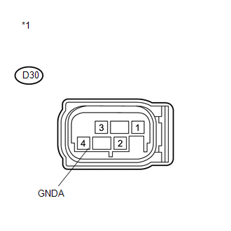
INSPECT YAW RATE AND ACCELERATION SENSOR (GNDA TERMINAL) |
|
(a) Turn the ignition switch off. |
|
(b) Measure the resistance according to the value(s) in the table below.
Standard Resistance:
|
Tester Connection |
Condition |
Specified Condition |
|---|---|---|
|
D30-4 (GNDA) - Body ground |
Always |
Below 1 Ω |
|
*1 |
Front view of wire harness connector (to Yaw Rate and Acceleration Sensor) |
HINT:
If troubleshooting has been carried out according to Problem Symptoms Table,
refer back to the table and proceed to the next step (See page
).
| OK | |
REPLACE YAW RATE AND ACCELERATION SENSOR |
| NG | |
REPAIR OR REPLACE HARNESS OR CONNECTOR (GNDA CIRCUIT) |
 Steering Angle Sensor Circuit Malfunction (C1231/31)
DESCRIPTION
The steering angle sensor signal is sent to the skid control ECU via the CAN
communication system. When there is a malfunction in the CAN communication system,
it will be detected by ...
 Engine Control System Malfunction (C1201/51)
DESCRIPTION
If a malfunction in the engine control system is detected, the operations of
VSC and TRAC are prohibited by the fail-safe function. When the signals from the
engine are input normally ...
Other materials about Toyota Venza:
Installation
INSTALLATION
PROCEDURE
1. INSTALL PARKING BRAKE SWITCH ASSEMBLY
(a) Install the parking brake switch assembly with the screw.
Torque:
0.9 N·m {9 kgf·cm, 8 in·lbf}
2. INSTALL PARKING BRAKE ...
Problem Symptoms Table
PROBLEM SYMPTOMS TABLE
HINT:
Use the table below to help determine the cause of problem symptoms.
If multiple suspected areas are listed, the potential causes of the symptoms
are listed in order of probability in the "Suspected Area" ...
Inspection
INSPECTION
PROCEDURE
1. INSPECT INTEGRATION RELAY
(a) Inner circuit (for 2GR-FE)
(1) for EFI MAIN relay
Measure the resistance according to the value(s) in the table
below.
Standard Resistance:
...

0.1345