Toyota Venza: Speaker Output Short (B15C3)
DESCRIPTION
This DTC is stored when a malfunction occurs in the speakers.
|
DTC No. |
DTC Detection Condition |
Trouble Area |
|---|---|---|
|
B15C3 |
A short is detected in the speaker output circuit |
|
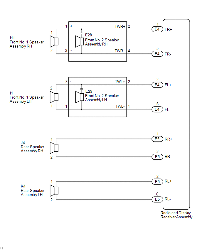
WIRING DIAGRAM
PROCEDURE
|
1. |
CHECK HARNESS AND CONNECTOR (RADIO AND DISPLAY RECEIVER ASSEMBLY - BODY GROUND) |
(a) Disconnect the E4 and E5 radio and display receiver assembly connectors.
(b) Disconnect the E28 and E29 front No. 2 speaker assembly connectors.
(c) Disconnect the J4 and K4 rear speaker assembly connectors.
(d) Measure the resistance between the radio and display receiver assembly and body ground to check for a short circuit in the wire harness.
Standard Resistance:
|
Tester Connection |
Condition |
Specified Condition |
|---|---|---|
|
E4-1 (FR+) - Body ground |
Always |
10 kΩ or higher |
|
E4-5 (FR-) - Body ground |
Always |
10 kΩ or higher |
|
E4-2 (FL+) - Body ground |
Always |
10 kΩ or higher |
|
E4-6 (FL-) - Body ground |
Always |
10 kΩ or higher |
|
E5-1 (RR+) - Body ground |
Always |
10 kΩ or higher |
|
E5-3 (RR-) - Body ground |
Always |
10 kΩ or higher |
|
E5-2 (RL+) - Body ground |
Always |
10 kΩ or higher |
|
E5-6 (RL-) - Body ground |
Always |
10 kΩ or higher |
| NG | .gif) |
REPAIR OR REPLACE HARNESS OR CONNECTOR |
|
.gif)
|
2. |
CHECK HARNESS AND CONNECTOR (FRONT NO. 2 SPEAKER ASSEMBLY - BODY GROUND) |
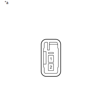
(a) Disconnect the H1 and I1 front No. 1 speaker assembly connectors.
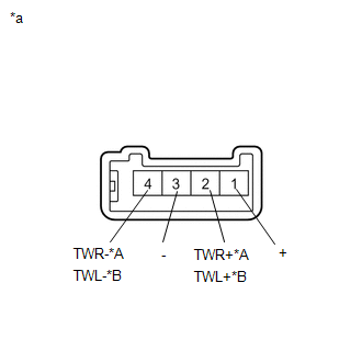
(b) Disconnect the E28 and E29 front No. 2 speaker assembly connectors.
(c) Measure the resistance between each of the front No. 2 speaker assemblies and body ground to check for a short circuit in the wire harness.
Standard Resistance:
|
Tester Connection |
Condition |
Specified Condition |
|---|---|---|
|
E28-1 (+) - Body ground |
Always |
10 kΩ or higher |
|
E28-3 (-) - Body ground |
Always |
10 kΩ or higher |
|
E29-1 (+) - Body ground |
Always |
10 kΩ or higher |
|
E29-3 (-) - Body ground |
Always |
10 kΩ or higher |
| NG | |
REPAIR OR REPLACE HARNESS OR CONNECTOR |
|
|
3. |
INSPECT FRONT NO. 1 SPEAKER ASSEMBLY |
(a) Remove the front No. 1 speaker assembly (See page
.gif) ).
).
|
(b) Measure the resistance according to the value(s) in the table below. Standard Resistance:
|
|
| NG | |
REPLACE FRONT NO. 1 SPEAKER ASSEMBLY |
|
|
4. |
INSPECT FRONT NO. 2 SPEAKER ASSEMBLY |
(a) Remove the front No. 2 speaker assembly (See page
).
|
(b) Measure the resistance according to the value(s) in the table below. Standard Resistance:
|
|
| NG | |
REPLACE FRONT NO. 2 SPEAKER ASSEMBLY |
|
|
5. |
REPLACE FRONT NO. 2 SPEAKER ASSEMBLY |
(a) Replace the front No. 2 speaker assembly with a new or known good one (See
page ).
(b) Clear the DTCs (See page ).
(c) Recheck for DTCs and check that no DTCs are output.
OK:
No DTCs are output.
HINT:
- Connect all the connectors to the front No. 2 speaker assemblies that were disconnected.
- When there is a possibility that either the right or left front No. 2 speaker assembly is defective, inspect by interchanging the right one with the left one.
- Perform the above inspection on both the LH and RH side.
| OK | |
END |
|
|
6. |
INSPECT REAR SPEAKER ASSEMBLY |
(a) Remove the rear speaker assembly (See page
).
|
(b) Measure the resistance according to the value(s) in the table below. Standard Resistance:
|
|
| OK | |
REPLACE RADIO AND DISPLAY RECEIVER ASSEMBLY |
| NG | |
REPLACE REAR SPEAKER ASSEMBLY |
 Main Body ECU Vehicle Information Reading/Writing Process Malfunction (B15F6)
DESCRIPTION
This DTC is stored when items controlled by the main body ECU (multiplex network
body ECU) cannot be customized via the audio and visual system vehicle customization
screen.
HINT: ...
 Short in GPS Antenna (B15C0,B15C1)
DESCRIPTION
These DTCs are stored when a malfunction occurs in the navigation antenna assembly.
DTC No.
DTC Detection Condition
Trouble Area
B15C0
...
Other materials about Toyota Venza:
Mass Air Flow Circuit Range / Performance Problem (P0101)
DESCRIPTION
Refer to DTC P0102 (See page ).
DTC No.
DTC Detection Condition
Trouble Area
P0101
All of the following conditions are met (2 trip detection logic):
(a) The engine is running.
(b ...
Rear Left Sensor Malfunction (C1AE6)
DESCRIPTION
The No. 1 ultrasonic sensor (rear left sensor) is installed on the rear bumper.
The ECU detects obstacles based on signals received from the No. 1 ultrasonic sensor
(rear left sensor). If the No. 1 ultrasonic sensor (rear left sensor) has an o ...
Removal
REMOVAL
CAUTION / NOTICE / HINT
HINT:
Use the same procedure for the RH side and LH side.
The procedure listed below is for the LH side.
PROCEDURE
1. REMOVE REAR WHEEL
2. SEPARATE REAR SPEED SENSOR
(a) Remove the bolt and se ...

0.1728