Toyota Venza: Control Module Performance (P0607)
MONITOR DESCRIPTION
The ECM continuously monitors its internal processors (CPUs) and heated oxygen sensor transistors. This self-check ensures that the ECM is functioning properly.
|
DTC No. |
DTC Detection Condition |
Trouble Area |
|---|---|---|
|
P0607 |
|
|
MONITOR STRATEGY
|
Related DTCs |
P0607: Control Module Performance |
|
Required Sensors/Components (Main) |
ECM |
|
Required Sensors/Components (Related) |
Heated oxygen sensor |
|
Frequency of Operation |
Continuous |
|
Duration |
60 seconds |
|
MIL Operation |
Immediate |
|
Sequence of Operation |
None |
TYPICAL ENABLING CONDITIONS
|
Monitor runs whenever the following DTCs are not stored |
None |
|
Engine |
Running |
|
Estimated heated oxygen sensor temperature |
450 to 750°C (842 to 1382°F) |
TYPICAL MALFUNCTION THRESHOLDS
|
Heated oxygen sensor transistors |
Fail |
CONFIRMATION DRIVING PATTERN
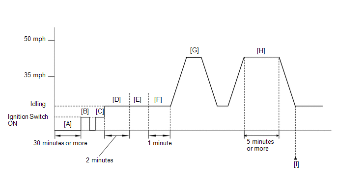
- Stop the engine for 30 minutes or more [A].
- Connect the Techstream to the DLC3.
- Turn the ignition switch to ON and turn the Techstream on [B].
- Clear DTCs (even if no DTCs are stored, perform the clear DTC operation)
(See page
.gif) ).
). - Turn the ignition switch off and wait for at least 30 seconds.
- Turn the ignition switch to ON and turn the Techstream on [C].
- Start the engine and wait 2 minutes [D].
- Warm up the engine until the engine coolant temperature is 75°C (167°F) or higher [E].
- Idle the engine for 1 minute [F].
- Accelerate the vehicle to 80 km/h (50 mph) and stop the vehicle [G].
CAUTION:
When performing the confirmation driving pattern, obey all speed limits and traffic laws.
- Drive the vehicle at 56 to 80 km/h (35 to 50 mph) for 5 minutes or more
[H].
CAUTION:
When performing the confirmation driving pattern, obey all speed limits and traffic laws.
- Enter the following menus: Powertrain / Engine / Trouble Codes [I].
- Read the pending DTCs.
HINT:
- If a pending DTC is output, the system is malfunctioning.
- If a pending DTC is not output, perform the following procedure.
- Enter the following menus: Powertrain / Engine / Utility / All Readiness.
- Input the DTC: P0607, P0136, P0137 or P0138.
- Check the DTC judgment result.
Techstream Display
Description
NORMAL
- DTC judgment completed
- System normal
ABNORMAL
- DTC judgment completed
- System abnormal
INCOMPLETE
- DTC judgment not completed
- Perform driving pattern after confirming DTC enabling conditions
N/A
- Unable to perform DTC judgment
- Number of DTCs which do not fulfill DTC preconditions has reached ECU memory limit
HINT:
- If the judgment result shows NORMAL, the system is normal.
- If the judgment result shows ABNORMAL, the system has a malfunction.
- If the judgment result shows INCOMPLETE or N/A, perform steps [E] through [I] again.
- If no pending DTC is output, perform a universal trip and check for
permanent DTCs (See page ).
HINT:
- If a permanent DTC is output, the system is malfunctioning.
- If no permanent DTC is output, the system is normal.
CAUTION / NOTICE / HINT
HINT:
Read freeze frame data using the Techstream. The ECM records vehicle and driving condition information as freeze frame data the moment a DTC is stored. When troubleshooting, freeze frame data can help determine if the vehicle was moving or stationary, if the engine was warmed up or not, if the air fuel ratio was lean or rich, and other data from the time the malfunction occurred.
PROCEDURE
|
1. |
CHECK ANY OTHER DTCS OUTPUT |
(a) Connect the Techstream to the DLC3.
(b) Turn the ignition switch to ON.
(c) Turn the Techstream on.
(d) Enter the following menus: Powertrain / Engine / Trouble Codes.
(e) Read the DTCs.
|
Result |
Proceed to |
|---|---|
|
P0607 and P0136, P0137 or P0138 are output |
A |
|
P0607 is output |
B |
| B | .gif) |
GO TO STEP 3 |
|
.gif)
|
2. |
INSPECT DTC (P0136, P0137 OR P0138) |
(a) Refer to the P0136, P0137 or P0138 flowchart.
HINT:
- If P0136 is output, troubleshoot for that DTC first (See page
). Then proceed to "INSPECT ECM".
- If P0137 is output, troubleshoot for that DTC first (See page
). Then proceed to "INSPECT ECM".
- If P0138 is output, troubleshoot for that DTC first (See page
). Then proceed to "INSPECT ECM".
- If DTC P0607 and P0136, P0137 or P0138 are output, the output voltage of the heated oxygen sensor may remain close to 0 V or become high (around 1 V or higher).
| NEXT | |
GO TO STEP 6 |
|
3. |
CHECK FOR EXHAUST GAS LEAK |
(a) Allow the engine to idle and rev the engine.
(b) Check for exhaust gas leaks around the heated oxygen sensor.
If any exhaust gas leaks are present, repair them and proceed to "PERFORM CONFIRMATION DRIVING PATTERN". If no exhaust gas leaks are present, proceed to "PERFORM CONFIRMATION DRIVING PATTERN".
HINT:
- If no exhaust gas leaks are present, a malfunction in the heated oxygen sensor circuit is suspected.
- If any exhaust gas leaks are present around the heated oxygen sensor, noise appears in the output voltage of the heated oxygen sensor.
- Perform "Inspection After Repair" after repairing or replacing the exhaust
system (See page ).
|
|
4. |
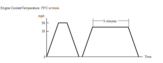
PERFORM CONFIRMATION DRIVING PATTERN |
(a) Clear the DTC (See page ).
(b) Connect the Techstream to the DLC3.
(c) Start the engine.
(d) Warm up the engine until the engine coolant temperature is 75°C (167°F) or higher.
(e) Perform the driving pattern.
(1) Accelerate the vehicle to 80 km/h (50 mph) and stop the vehicle.
(2) Drive the vehicle between 56 and 80 km/h (35 and 50 mph) for 5 minutes.
(f) Enter the following menus: Powertrain / Engine / Trouble Codes / Pending.
(g) Read the pending DTCs.
|
Result |
Proceed to |
|---|---|
|
P0136, P0137, P0138 and/or P0607 |
A |
|
Only P0607 |
B |
|
No DTC output |
C |
| B | |
REPLACE ECM |
| C | |
GO TO STEP 6 |
|
|
5. |
INSPECT DTC (P0136, P0137 OR P0138) |
(a) Refer to the P0136, P0137 or P0138 flowchart.
HINT:
- If P0136 is output, troubleshoot for that DTC first (See page
). Then proceed to "INSPECT ECM".
- If P0137 is output, troubleshoot for that DTC first (See page
). Then proceed to "INSPECT ECM".
- If P0138 is output, troubleshoot for that DTC first (See page
). Then proceed to "INSPECT ECM".
- If DTC P0607 and P0136, P0137 or P0138 are output, the output voltage of the heated oxygen sensor may remain close to 0 V or become high (around 1 V or higher).
|
|
6. |
INSPECT ECM |
(a) Clear the DTC (See page ).
(b) Stop the engine and wait for 30 minutes.
(c) Connect the Techstream to the DLC3.
(d) Start the engine and allow it to idle for 2 minutes.
(e) Turn the Techstream on.
(f) Enter the following menus: Powertrain / Engine / Trouble Codes.
(g) Check the DTCs.
|
Result |
Proceed to |
|---|---|
|
DTC is not output |
A |
|
P0607 is output |
B |
| A | |
END |
| B | |
REPLACE ECM |
 ECM / PCM Processor (P0606)
MONITOR DESCRIPTION
The ECM continuously monitors its main and sub CPUs. This self-check ensures
that the ECM is functioning properly. If outputs from the CPUs are different and
deviate from the ...
 Internal Control Module Monitoring Processor Performance (P060A)
MONITOR DESCRIPTION
The main CPU and sub CPU of the ECM perform data communication between each other.
The main CPU monitors the communications and WDC pulses from the sub CPU. When the
signal ma ...
Other materials about Toyota Venza:
Front Blower Motor
Components
COMPONENTS
ILLUSTRATION
Installation
INSTALLATION
PROCEDURE
1. INSTALL FRONT BLOWER MOTOR SUB-ASSEMBLY
(a) Install the front blower motor sub-assembly with the 3 screws.
(b) Con ...
Removal
REMOVAL
CAUTION / NOTICE / HINT
HINT:
Use the same procedure for the RH side and LH side.
The procedure listed below is for the LH side.
PROCEDURE
1. REMOVE REAR WHEEL
2. SEPARATE REAR DISC BRAKE CALIPER ASSEMBLY
3. REMOVE REAR DISC ...
Reassembly
REASSEMBLY
PROCEDURE
1. INSTALL NO. 2 STEERING RACK BOOT
(a) Apply lithium soap base glycol grease to the inside of the small
opening of a new No. 2 steering rack boot.
(b) Install the No. 2 ste ...

0.1237