Toyota Venza: Main Body Ecu
Components
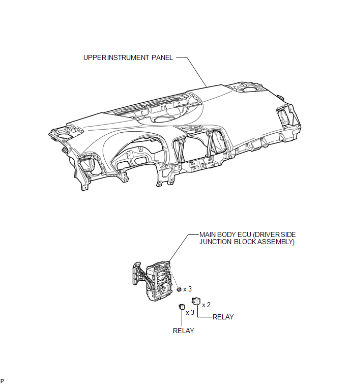
COMPONENTS
ILLUSTRATION
Removal
REMOVAL
PROCEDURE
1. REMOVE UPPER INSTRUMENT PANEL
HINT:
Refer to the procedure up to Remove Upper Instrument Panel Sub-assembly (See
page .gif) ).
).
2. REMOVE MAIN BODY ECU (DRIVER SIDE JUNCTION BLOCK ASSEMBLY)
|
(a) Disconnect the 4 connectors. |
|
|
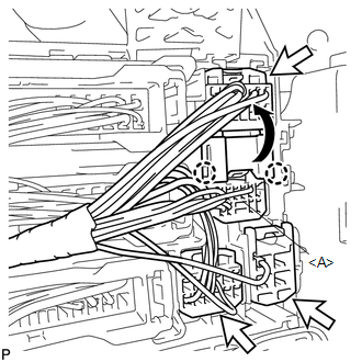
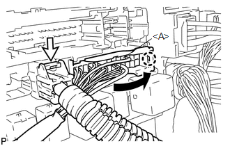
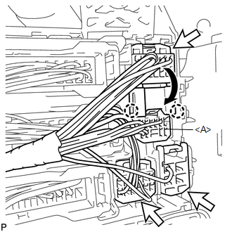
(b) Disengage the 2 claws and disconnect the connector <A> as shown in the illustration. |
|
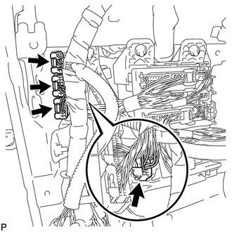
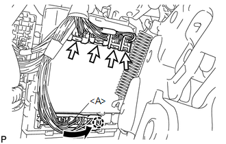
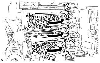
(c) Disconnect the 3 connectors.
|
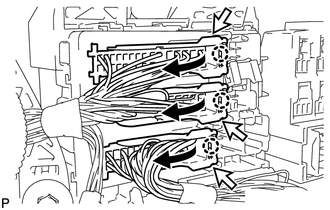
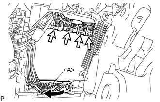
(d) Disconnect the 3 connectors as shown in the illustration. |
|
|
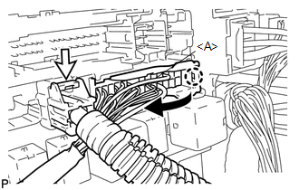
(e) Disconnect the connector <A> as shown in the illustration. |
|
(f) Disconnect the connector.
|
(g) Disconnect the 2 connectors. |
|
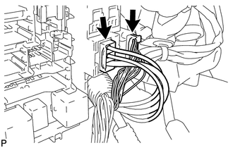
|
(h) Remove the 3 nuts. |
|
(i) Disengage the 2 claws.
|
(j) Disconnect the connector <A> as shown in the illustration. |
|
(k) Disconnect the 4 connectors and remove the main body ECU (driver side junction block assembly).
|
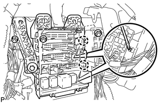
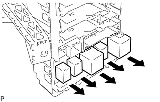
(l) Remove the 5 relays. |
|
Installation
INSTALLATION
PROCEDURE
1. INSTALL MAIN BODY ECU (DRIVER SIDE JUNCTION BLOCK ASSEMBLY)
|
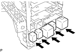
(a) Install the 5 relays. |
|
|
(b) Connect the 4 connectors. |
|
(c) Connect the connector <A> as shown in the illustration.
NOTICE:
Be sure to engage each connector securely.
|
(d) Engage the 2 claws. |
|
.png)
(e) Install the 3 nuts and install the main body ECU (driver side junction block assembly).
|
(f) Connect the 2 connectors. NOTICE: Be sure to engage the connector securely. |
|
.png)
|
(g) Connect the connector <A> as shown in the illustration. NOTICE: Be sure to engage the connector securely. |
|
(h) Connect the connector.
NOTICE:
Be sure to engage each connector securely.
|
(i) Connect the 3 connectors as shown in the illustration. NOTICE: Be sure to engage each connector securely. |
|
|
(j) Engage the 2 claws to connect the connector <A> as shown in the illustration. NOTICE: Be sure to engage the connector securely. |
|
(k) Connect the 3 connectors.
NOTICE:
Be sure to engage each connector securely.
|
(l) Connect the 4 connectors. NOTICE: Be sure to engage each connector securely. |
|
.png)
2. INSTALL UPPER INSTRUMENT PANEL
HINT:
Refer to the procedure from Install Upper Instrument Panel Sub-assembly (See
page .gif) ).
).
 Installation
INSTALLATION
PROCEDURE
1. INSTALL POWER DISTRIBUTION
(a) Connect the 3 connectors.
(b) Engage the 2 claws to temporarily instal ...
 Power Management Control Ecu
Components
COMPONENTS
ILLUSTRATION
Removal
REMOVAL
PROCEDURE
1. REMOVE FRONT DOOR SCUFF PLATE RH
2. REMOVE COWL SIDE TRIM SUB-ASSEMBLY RH
3. REMOVE NO. 2 INSTRUMENT PANEL UNDER COV ...
Other materials about Toyota Venza:
Lost Communication with TCM (U0101)
DESCRIPTION
The Transmission Control Module (TCM) and ECM perform 2-way communication with
each other via the Controller Area Network (CAN). The TCM sends signals to the ECM
concerning required engine speed, required engine torque, warning indicators in
...
Removal
REMOVAL
CAUTION / NOTICE / HINT
CAUTION:
Wear protective gloves when removing the exhaust pipe.
The exhaust pipe is extremely hot immediately after the engine has stopped.
Confirm that the exhaust pipe has cooled down ...
Intake Manifold Runner Control Circuit Low (Bank 1) (P2009,P2010)
DESCRIPTION
The ECM activates the DC motor for the tumble control valve, which opens and
closes the tumble control valve. The ECM activates the DC motor based on engine
speed, coolant temperature, intake air temperature and other conditions.
D ...

0.146