Toyota Venza: Lost Communication with Automatic High Beam Sensor (B2432)
DESCRIPTION
The DTC is stored when the AFS ECU (headlight swivel ECU assembly) detects malfunctions in the LIN communication system.
|
DTC No. |
DTC Detection Condition |
Trouble Area |
|---|---|---|
|
B2432 |
Malfunction in LIN communication system |
|
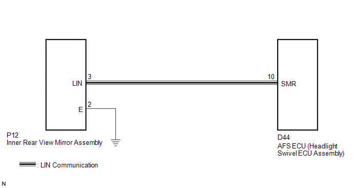
WIRING DIAGRAM
PROCEDURE
|
1. |
CHECK FOR DTC |
(a) Clear the DTCs (See page .gif) ).
).
(b) Check for DTCs (See page ).
OK:
DTC B2432 is not output.
| OK | .gif) |
USE SIMULATION METHOD TO CHECK |
|
.gif)
|
2. |
CHECK HARNESS AND CONNECTOR (AFS ECU (HEADLIGHT SWIVEL ECU ASSEMBLY) - HEADLIGHT ASSEMBLY) |
(a) Disconnect the D44 AFS ECU (headlight swivel ECU assembly) connector.
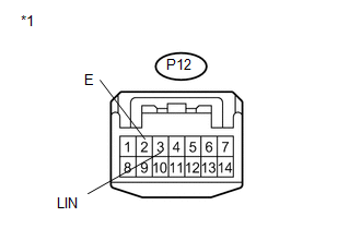
(b) Disconnect the P12 inner rear view mirror assembly connector.
(c) Measure the resistance according to the value(s) in the table below.
Standard Resistance:
|
Tester Connection |
Condition |
Specified Condition |
|---|---|---|
|
D44-10 (SMR) - P12-3 (LIN) |
Always |
Below 1 Ω |
|
P12-3 (LIN) - Body ground |
Always |
10 kΩ or higher |
| NG | |
REPAIR OR REPLACE HARNESS OR CONNECTOR |
|
|
3. |
INSPECT AFS ECU (HEADLIGHT SWIVEL ECU ASSEMBLY) |
(a) Reconnect the D44 AFS ECU (headlight swivel ECU assembly) connector.
|
(b) Connect an oscilloscope to the P12 inner rear view mirror assembly connector. |
|
|
(c) Check the waveform. OK:
|
|
.png)
| OK | |
REPLACE INNER REAR VIEW MIRROR ASSEMBLY |
| NG | |
REPLACE AFS ECU (HEADLIGHT SWIVEL ECU ASSEMBLY) |
 Vehicle Specifications have not been Stored (B2451)
DESCRIPTION
The headlight leveling ECU assembly stores this DTC if the vehicle specifications
have not been stored in the ECU.
HINT:
The vehicle specifications are stored in the ECU at the factor ...
 Initialization has not been Performed (B2450)
DESCRIPTION
The headlight leveling ECU assembly stores this DTC if initialization has not
been performed after the ECU was replaced.
DTC No.
DTC Detecting Condition
...
Other materials about Toyota Venza:
Stop Light Control Relay Malfunction (C1380/64)
DESCRIPTION
Upon receiving the hill-start assist control operating signal from the skid control
ECU, the relay contact turns on and the stop light comes on.
DTC Code
DTC Detection Condition
Trouble Area
C13 ...
Removal
REMOVAL
PROCEDURE
1. DISCONNECT CABLE FROM NEGATIVE BATTERY TERMINAL
CAUTION:
Wait at least 90 seconds after disconnecting the cable from the negative (-)
battery terminal to disable the SRS system.
NOTICE:
When disconnecting the cable, some systems ne ...
Precaution
PRECAUTION
1. PRECAUTION FOR DISCONNECTING CABLE FROM NEGATIVE BATTERY TERMINAL
NOTICE:
When disconnecting the cable from the negative (-) battery terminal, initialize
the following system after the cable is reconnected.
System Name
...

0.1372