Toyota Venza: Removal
REMOVAL
CAUTION / NOTICE / HINT
HINT:
- Use the same procedure for the RH side and LH side.
- The procedure listed below is for the LH side.
PROCEDURE
1. REMOVE REAR WHEEL
2. SEPARATE REAR SPEED SENSOR
.gif)
3. REMOVE REAR AXLE SHAFT NUT
4. SEPARATE REAR DISC BRAKE CALIPER ASSEMBLY
5. REMOVE REAR DISC
6. REMOVE REAR AXLE HUB AND BEARING ASSEMBLY
7. SEPARATE NO. 3 PARKING BRAKE CABLE ASSEMBLY
8. REMOVE REAR STRUT ROD ASSEMBLY
9. REMOVE REAR AXLE CARRIER SUB-ASSEMBLY
|
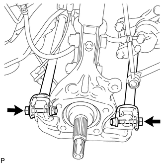
(a) Loosen the 2 bolts. NOTICE: Since stopper nuts are used, loosen the bolts. |
|
|
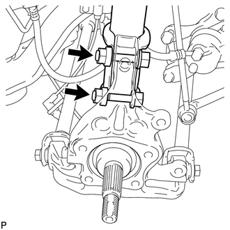
(b) Remove the 2 bolts and 2 nuts, and separate the rear shock absorber with coil spring (lower side) from the rear axle carrier sub-assembly. NOTICE:
|
|
|
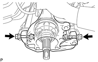
(c) Remove the 2 bolts, 2 nuts and rear axle carrier sub-assembly. NOTICE:
|
|
 Components
COMPONENTS
ILLUSTRATION
...
 Installation
INSTALLATION
CAUTION / NOTICE / HINT
HINT:
Use the same procedure for the RH side and LH side.
The procedure listed below is for the LH side.
PROCEDURE
1. INSTALL REAR AXLE CARR ...
Other materials about Toyota Venza:
Power Window Switch Malfunction (B2312)
DESCRIPTION
The power window regulator motor assembly is operated by the power window regulator
master switch assembly or power window regulator switch assembly. The power window
regulator motor assembly has motor, regulator and ECU functions.
This DTC i ...
Door Courtesy Light
Components
COMPONENTS
ILLUSTRATION
Removal
REMOVAL
PROCEDURE
1. REMOVE COURTESY LIGHT ASSEMBLY
(a) Using a screwdriver wrapped with protective tape, disengage the claw.
Text in Illustration
*1
Pro ...
Motor Circuit Malfunction (C1521,C1531-C1534,C1554)
DESCRIPTION
If the power steering ECU detects these DTCs, it will shut off the motor relay
circuit (built into the power steering ECU) and stop power assist. However, power
assist continues if DTC C1533 or C1534 is stored.
DTC No.
D ...

0.1585