Toyota Venza: License Plate Light Assembly
Components
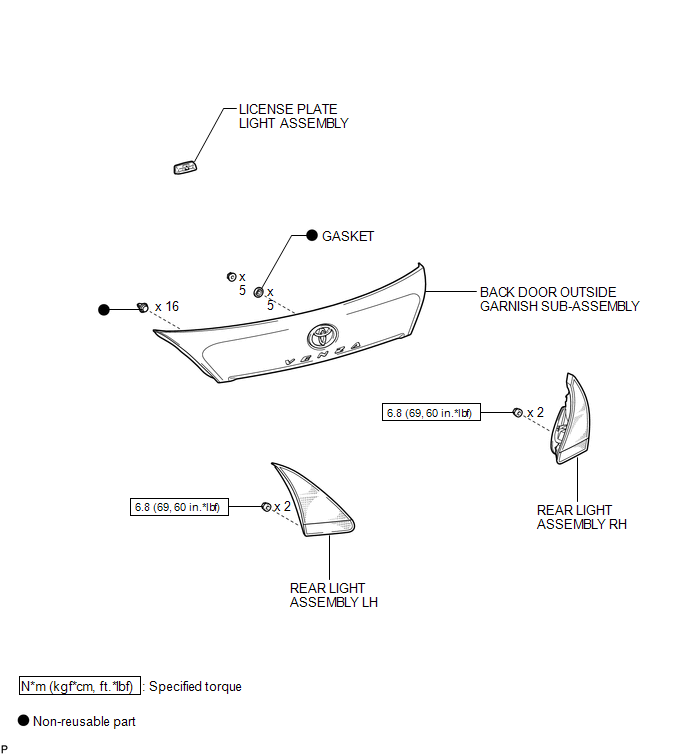
COMPONENTS
ILLUSTRATION
.png)
ILLUSTRATION
Installation
INSTALLATION
PROCEDURE
1. INSTALL LICENSE PLATE LIGHT ASSEMBLY
|
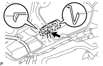
(a) Engage the 2 claws to install the license plate light assembly. |
|
(b) Connect the connector.
2. INSTALL BACK DOOR OUTSIDE GARNISH SUB-ASSEMBLY
.gif)
3. INSTALL REAR LIGHT ASSEMBLY LH
4. INSTALL REAR LIGHT ASSEMBLY RH
HINT:
Use the same procedure for the RH side and LH side.
5. INSTALL REAR WIPER MOTOR AND BRACKET ASSEMBLY
6. INSTALL REAR WIPER MOTOR GROMMET
7. INSTALL REAR WIPER ARM AND BLADE ASSEMBLY
8. INSTALL REAR WIPER ARM HEAD CAP
9. INSTALL BACK DOOR PANEL TRIM ASSEMBLY
Removal
REMOVAL
PROCEDURE
1. REMOVE BACK DOOR PANEL TRIM ASSEMBLY
.gif)
2. REMOVE REAR WIPER ARM HEAD CAP
3. REMOVE REAR WIPER ARM AND BLADE ASSEMBLY
4. REMOVE REAR WIPER MOTOR GROMMET
5. REMOVE REAR WIPER MOTOR AND BRACKET ASSEMBLY
6. REMOVE REAR LIGHT ASSEMBLY LH
7. REMOVE REAR LIGHT ASSEMBLY RH
HINT:
Use the same procedure for the RH side and LH side.
8. REMOVE BACK DOOR OUTSIDE GARNISH SUB-ASSEMBLY
9. REMOVE LICENSE PLATE LIGHT ASSEMBLY
|
(a) Disconnect the connector. |
|
.png)
(b) Disengage the 2 claws and remove the license plate light assembly.
 High Mounted Stop Light Assembly
Components
COMPONENTS
ILLUSTRATION
Removal
REMOVAL
PROCEDURE
1. REMOVE CENTER STOP LIGHT ASSEMBLY
(a) Using a short screwdriver, remove the 2 screws.
...
 Lighting System
...
Other materials about Toyota Venza:
LIN Communication Bus Malfunction (B2325)
DESCRIPTION
The main body ECU (driver side junction block assembly) monitors communication
between all the ECUs connected to the door bus lines. When the main body ECU (driver
side junction block assembly) detects errors in communication with all the ECUs ...
Disassembly
DISASSEMBLY
PROCEDURE
1. DISCONNECT CABLE FROM NEGATIVE BATTERY TERMINAL
NOTICE:
When disconnecting the cable, some systems need to be initialized after the cable
is reconnected (See page ).
2. REMOVE REAR DOOR INSIDE HANDLE BEZEL PLUG
(a) ...

0.1229