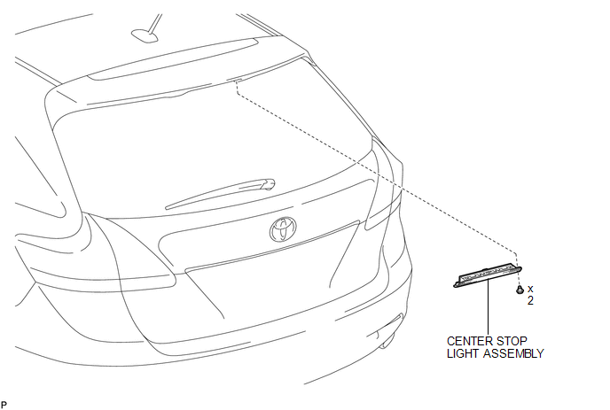
Toyota Venza: High Mounted Stop Light Assembly
Components
COMPONENTS
ILLUSTRATION
Removal
REMOVAL
PROCEDURE
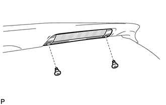
1. REMOVE CENTER STOP LIGHT ASSEMBLY
|
(a) Using a short screwdriver, remove the 2 screws. |
|
(b) Disconnect the connector and remove the center stop light assembly.
Inspection
INSPECTION
PROCEDURE
1. INSPECT CENTER STOP LIGHT ASSEMBLY
|
(a) Connect a positive (+) lead from the battery to terminal 2 and a negative (-) lead to terminal 1. |
|
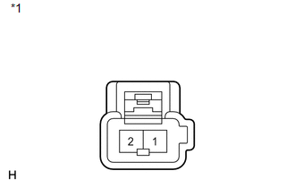
(b) Check that the light comes on.
OK:
The light comes on.
Text in Illustration|
*1 |
Component without harness connected (Center Stop Light Assembly) |
If the result is not as specified, replace the center stop light assembly.
Installation
INSTALLATION
PROCEDURE
1. INSTALL CENTER STOP LIGHT ASSEMBLY
(a) Connect the connector.
|
(b) Using a short screwdriver, install the center stop light assembly with the 2 screws. |
|
.png)
 Removal
REMOVAL
CAUTION / NOTICE / HINT
PROCEDURE
1. PRECAUTION
NOTICE:
After turning the ignition switch off, waiting time may be required before disconnecting
the cable from the negative (-) battery ...
 License Plate Light Assembly
Components
COMPONENTS
ILLUSTRATION
ILLUSTRATION
Installation
INSTALLATION
PROCEDURE
1. INSTALL LICENSE PLATE LIGHT ASSEMBLY
(a) Engage the 2 claws to install the license pla ...
Other materials about Toyota Venza:
How To Proceed With Troubleshooting
CAUTION / NOTICE / HINT
HINT:
Use the following procedure to troubleshoot the power door lock control
system.
*: Use the Techstream.
PROCEDURE
1.
VEHICLE BROUGHT TO WORKSHOP
NEXT ...
Weight limits
• The gross trailer weight must never exceed TWR described in the table. • The
gross combination weight must never exceed the GCWR described in the table.
• The gross vehicle weight must never exceed the GVWR indicated on the Certification
Label. ...
Rocker Panel Moulding
Components
COMPONENTS
ILLUSTRATION
Removal
REMOVAL
PROCEDURE
1. REMOVE FRONT FENDER OUTSIDE MOULDING
2. REMOVE NO. 2 ROCKER PANEL MOULDING PROTECTOR
3. REMOVE REAR ROCKER PANEL MOULDING END COVER
4. REMOVE BODY ROCKER PANEL MOULDING ASS ...

0.1141