Toyota Venza: Front Passenger Side Power Window Switch
Components
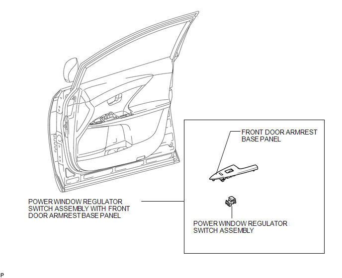
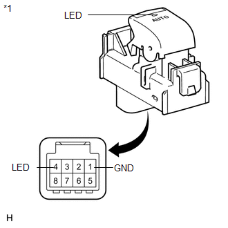
COMPONENTS
ILLUSTRATION
Removal
REMOVAL
PROCEDURE
1. REMOVE POWER WINDOW REGULATOR SWITCH ASSEMBLY WITH FRONT DOOR ARMREST BASE PANEL
|
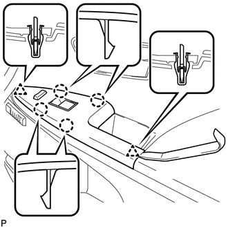
(a) Using a moulding remover, disengage the 2 clips and 4 claws. |
|
(b) Disconnect the connector and remove the power window regulator switch assembly with front door armrest base panel.
2. REMOVE POWER WINDOW REGULATOR SWITCH ASSEMBLY
|
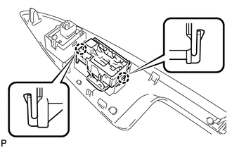
(a) Disengage the 2 claws and remove the power window regulator switch assembly. |
|
Inspection
INSPECTION
PROCEDURE
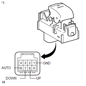
1. INSPECT POWER WINDOW REGULATOR SWITCH ASSEMBLY
|
(a) Check the switch function. (1) Measure the resistance according to the value(s) in the table below. Standard Resistance:
If the result is not as specified, replace the power window regulator switch assembly (for front passenger side). |
|
|
(b) Check that the LED illuminates. (1) Apply battery voltage to the power window regulator switch assembly and check that the LED illuminates. OK:
If the result is not as specified, replace the power window regulator switch assembly (for front passenger side). |
|
Installation
INSTALLATION
PROCEDURE
1. INSTALL POWER WINDOW REGULATOR SWITCH ASSEMBLY
|
(a) Engage the 2 claws to install the power window regulator switch assembly. |
|
.png)
2. INSTALL POWER WINDOW REGULATOR SWITCH ASSEMBLY WITH FRONT DOOR ARMREST BASE PANEL
|
(a) Connect the connector. |
|
(b) Engage the 2 clips and 4 claws, and install the power window regulator switch assembly with front door armrest base panel.
 Removal
REMOVAL
PROCEDURE
1. REMOVE UPPER BACK WINDOW PANEL TRIM
2. REMOVE BACK DOOR PANEL TRIM ASSEMBLY
3. DISCONNECT POWER BACK DOOR ROD (w/ Power Back Door)
4. REMOVE BACK DOOR TRIM COVER LH ...

Other materials about Toyota Venza:
If you think something is wrong
If you notice any of the following symptoms, your vehicle probably needs adjustment
or repair. Contact your Toyota dealer as soon as possible.
- Visible symptoms
• Fluid leaks under the vehicle
(Water dripping from the air conditioning after use i ...
How To Proceed With Troubleshooting
CAUTION / NOTICE / HINT
HINT:
Use the following procedure listed to troubleshoot the Active Torque
Control 4WD system.
*: Use the Techstream.
PROCEDURE
1.
VEHICLE BROUGHT TO WORKSHOP
...
Security Horn Assembly
Removal
REMOVAL
PROCEDURE
1. REMOVE SECURITY HORN ASSEMBLY
(a) Remove the bolt and disconnect the security horn assembly.
(b) Disconnect the connector and remove the security horn asse ...

0.1647