Toyota Venza: Speaker Circuit
DESCRIPTION
- If there is a short in a speaker circuit, the radio and display receiver assembly detects it and stops output to the speakers.
- Thus sound cannot be heard from the speakers even if there is no malfunction in the radio and display receiver assembly or speakers.
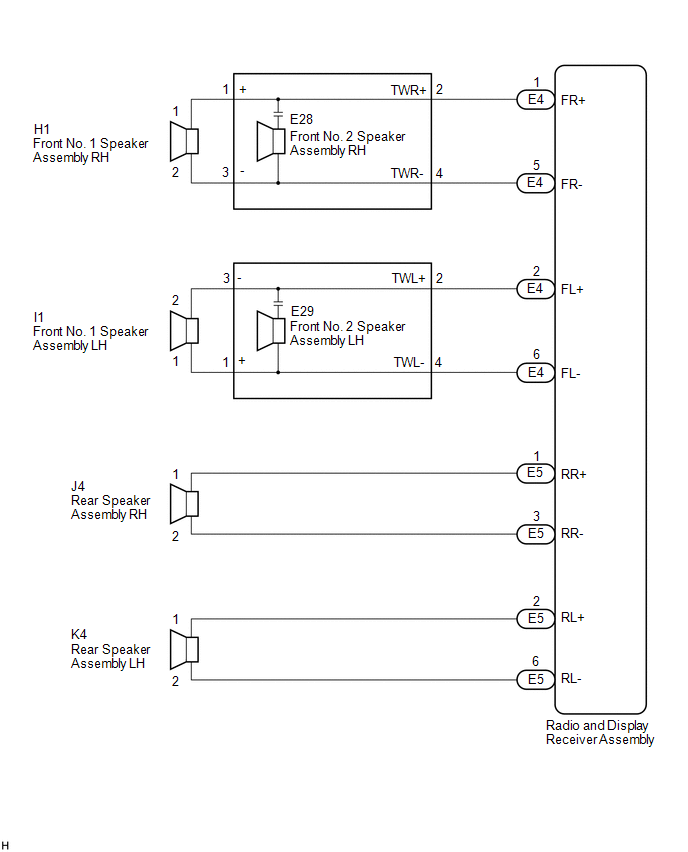
WIRING DIAGRAM
PROCEDURE
|
1. |
CHECK SPEAKER (OPERATION CHECK) |
|
(a) Enter the "System Check Mode" screen. Refer to Check Speaker in Operation
Check (See page |
|
.png)
(b) Perform the operation check above and determine the speaker that is not operating.
|
Result |
Proceed to |
|---|---|
|
Front No. 1 speaker assembly or front No. 2 speaker assembly |
A |
|
Rear speaker assembly |
B |
HINT:
If sound cannot be heard from any speaker, inspect all of them.
| B | .gif) |
GO TO STEP 7 |
|
.gif)
|
2. |
CHECK HARNESS AND CONNECTOR (RADIO AND DISPLAY RECEIVER ASSEMBLY - FRONT NO. 2 SPEAKER ASSEMBLY) |
(a) Disconnect the E4 radio and display receiver assembly connector.
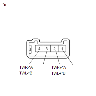
(b) Disconnect the E28 and E29 front No. 2 speaker assembly connectors.
(c) Measure the resistance between each of the front No. 2 speaker assemblies and the radio and display receiver assembly to check for an open circuit in the wire harness.
Standard Resistance:
|
Tester Connection |
Condition |
Specified Condition |
|---|---|---|
|
E4-1 (FR+) - E28-2 (TWR+) |
Always |
Below 1 Ω |
|
E4-5 (FR-) - E28-4 (TWR-) |
Always |
Below 1 Ω |
|
E4-2 (FL+) - E29-2 (TWL+) |
Always |
Below 1 Ω |
|
E4-6 (FL-) - E29-4 (TWL-) |
Always |
Below 1 Ω |
(d) Measure the resistance between the radio and display receiver assembly and body ground to check for a short circuit in the wire harness.
Standard Resistance:
|
Tester Connection |
Condition |
Specified Condition |
|---|---|---|
|
E4-1 (FR+) - Body ground |
Always |
10 kΩ or higher |
|
E4-5 (FR-) - Body ground |
Always |
10 kΩ or higher |
|
E4-2 (FL+) - Body ground |
Always |
10 kΩ or higher |
|
E4-6 (FL-) - Body ground |
Always |
10 kΩ or higher |
| NG | |
REPAIR OR REPLACE HARNESS OR CONNECTOR |
|
|
3. |
CHECK HARNESS AND CONNECTOR (FRONT NO. 1 SPEAKER ASSEMBLY - FRONT NO. 2 SPEAKER ASSEMBLY) |
(a) Disconnect the E28 and E29 front No. 2 speaker assembly connectors.
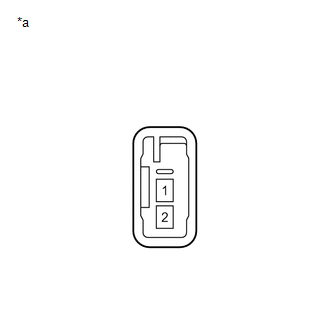
(b) Disconnect the H1 and I1 front No. 1 speaker assembly connectors.
(c) Measure the resistance between each of the front No. 1 speaker assemblies and the front No. 2 speaker assemblies to check for an open circuit in the wire harness.
Standard Resistance:
|
Tester Connection |
Condition |
Specified Condition |
|---|---|---|
|
E28-1 (+) - H1-1 |
Always |
Below 1 Ω |
|
E28-3 (-) - H1-2 |
Always |
Below 1 Ω |
|
E29-1 (+) - I1-1 |
Always |
Below 1 Ω |
|
E29-3 (-) - I1-2 |
Always |
Below 1 Ω |
(d) Measure the resistance between each of the front No. 2 speaker assemblies and body ground to check for a short circuit in the wire harness.
Standard Resistance:
|
Tester Connection |
Condition |
Specified Condition |
|---|---|---|
|
E28-1 (+) - Body ground |
Always |
10 kΩ or higher |
|
E28-3 (-) - Body ground |
Always |
10 kΩ or higher |
|
E29-1 (+) - Body ground |
Always |
10 kΩ or higher |
|
E29-3 (-) - Body ground |
Always |
10 kΩ or higher |
| NG | |
REPAIR OR REPLACE HARNESS OR CONNECTOR |
|
|
4. |
INSPECT FRONT NO. 2 SPEAKER ASSEMBLY |
(a) Remove the front No. 2 speaker assembly (See Page
.gif) ).
).
|
(b) Measure the resistance according to the value(s) in the table below. Standard Resistance:
|
|
| NG | |
REPLACE FRONT NO. 2 SPEAKER ASSEMBLY |
|
|
5. |
REPLACE FRONT NO. 2 SPEAKER ASSEMBLY |
(a) Check that the malfunction disappears when a new or known good speaker is
installed (See page ).
OK:
Malfunction disappears.
HINT:
- Connect all the connectors to the front No. 2 speaker assemblies that were disconnected.
- When there is a possibility that either the right or left front No. 2 speaker assembly is defective, inspect by interchanging the right one with the left one.
- Perform the above inspection on both the LH and RH side.
| OK | |
END (FRONT NO. 2 SPEAKER ASSEMBLY WAS DEFECTIVE) |
|
|
6. |
INSPECT FRONT NO. 1 SPEAKER ASSEMBLY |
(a) Remove the front No. 1 speaker assembly (See page
).
|
(b) Measure the resistance according to the value(s) in the table below. Standard Resistance:
|
|
| OK | |
PROCEED TO NEXT SUSPECTED AREA SHOWN IN PROBLEM SYMPTOMS TABLE |
| NG | |
REPLACE FRONT NO. 1 SPEAKER ASSEMBLY |
|
7. |
CHECK HARNESS AND CONNECTOR (RADIO AND DISPLAY RECEIVERASSEMBLY - REAR SPEAKER ASSEMBLY) |
(a) Disconnect the E5 radio and display receiver assembly connector.
(b) Disconnect the J4 and K4 rear speaker assembly connectors.
(c) Measure the resistance between each of the rear speaker assemblies and the radio and display receiver assembly to check for an open circuit in the wire harness.
Standard Resistance:
|
Tester Connection |
Condition |
Specified Condition |
|---|---|---|
|
E5-1 (RR+) - J4-1 |
Always |
Below 1 Ω |
|
E5-3 (RR-) - J4-2 |
Always |
Below 1 Ω |
|
E5-2 (RL+) - K4-1 |
Always |
Below 1 Ω |
|
E5-6 (RL-) - K4-2 |
Always |
Below 1 Ω |
(d) Measure the resistance between the radio and display receiver assembly and body ground to check for a short circuit in the wire harness.
Standard Resistance:
|
Tester Connection |
Condition |
Specified Condition |
|---|---|---|
|
E5-1 (RR+) - Body ground |
Always |
10 kΩ or higher |
|
E5-3 (RR-) - Body ground |
Always |
10 kΩ or higher |
|
E5-2 (RL+) - Body ground |
Always |
10 kΩ or higher |
|
E5-6 (RL-) - Body ground |
Always |
10 kΩ or higher |
| NG | |
REPAIR OR REPLACE HARNESS OR CONNECTOR |
|
|
8. |
INSPECT REAR SPEAKER ASSEMBLY |
(a) Remove the rear speaker assembly (See Page
).
|
(b) Measure the resistance according to the value(s) in the table below. Standard Resistance:
|
|

| OK | |
PROCEED TO NEXT SUSPECTED AREA SHOWN IN PROBLEM SYMPTOMS TABLE |
| NG | |
REPLACE REAR SPEAKER ASSEMBLY |
 Parking Brake Switch Circuit
DESCRIPTION
This circuit is from the parking brake switch assembly to the radio and display
receiver assembly.
WIRING DIAGRAM
PROCEDURE
1.
CHECK BRAKE WARNING LIGHT
...
 Sound Signal Circuit between Radio Receiver and Stereo Jack Adapter
DESCRIPTION
The No. 1 stereo jack adapter assembly sends the sound signal from an
external device to the radio and display receiver assembly via this circuit.
The sound signal that has ...
Other materials about Toyota Venza:
Precaution
PRECAUTION
NOTICE:
When disconnecting the cable from the negative (-) battery terminal, initialize
the following systems after the cable is reconnected.
System Name
See Procedure
Back Door Closer System
...
Removal
REMOVAL
PROCEDURE
1. REMOVE RADIATOR ASSEMBLY AND FAN ASSEMBLY WITH MOTOR
HINT:
See page
2. REMOVE FAN
(a) Remove the nut and fan.
3. REMOVE NO. 2 FAN
(a) Remove the nut and No. 2 f ...
On-vehicle Inspection
ON-VEHICLE INSPECTION
PROCEDURE
1. INSPECT WINDSHIELD WIPER MOTOR ASSEMBLY
(a) for RH Side
(1) Operate the windshield wiper motor assembly.
(2) Stop the windshield wiper motor assembly operation.
...

0.1381