Toyota Venza: Voice Recognition Microphone Disconnected (B1579)
DESCRIPTION
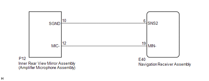
The navigation receiver assembly and inner rear view mirror assembly (amplifier microphone assembly) are connected to each other using the microphone connection detection signal lines.
This DTC is stored when a microphone connection detection signal line is disconnected.
|
DTC No. |
DTC Detection Condition |
Trouble Area |
|---|---|---|
|
B1579 |
Telephone microphone signal is lost. |
|
WIRING DIAGRAM
PROCEDURE
|
1. |
INSPECT NAVIGATION RECEIVER ASSEMBLY |
|
(a) Measure the resistance according to the value(s) in the table below. Standard Resistance:
|
|
| NG | .gif) |
REPLACE NAVIGATION RECEIVER ASSEMBLY |
|
.gif)
|
2. |
CHECK HARNESS AND CONNECTOR (NAVIGATION RECEIVER ASSEMBLY - INNER REAR VIEW MIRROR ASSEMBLY (AMPLIFIER MICROPHONE ASSEMBLY)) |
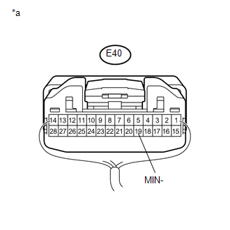
(a) Disconnect the E40 navigation receiver assembly connector.
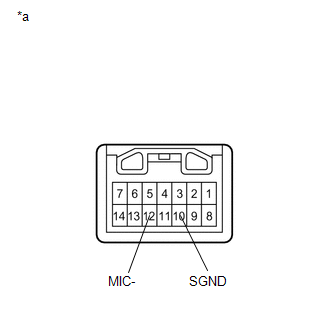
(b) Disconnect the P12 inner rear view mirror assembly (amplifier microphone assembly) connector.
(c) Measure the resistance according to the value(s) in the table below.
Standard Resistance:
|
Tester Connection |
Condition |
Specified Condition |
|---|---|---|
|
E40-6 (SNS2) - P12-10 (SGND) |
Always |
Below 1 Ω |
|
E40-19 (MIN-) - P12-12 (MIC-) |
Always |
Below 1 Ω |
|
E40-6 (SNS2) - Body ground |
Always |
10 kΩ or higher |
|
E40-19 (MIN-) - Body ground |
Always |
10 kΩ or higher |
| NG | |
REPAIR OR REPLACE HARNESS OR CONNECTOR |
|
|
3. |
INSPECT INNER REAR VIEW MIRROR ASSEMBLY (AMPLIFIER MICROPHONE ASSEMBLY) |
(a) Remove the inner rear view mirror assembly (amplifier microphone assembly)
(See page .gif) ).
).
|
(b) Measure the resistance according to the value(s) in the table below. Standard Resistance:
|
|
| OK | |
REPLACE NAVIGATION RECEIVER ASSEMBLY |
| NG | |
REPLACE INNER REAR VIEW MIRROR ASSEMBLY (AMPLIFIER MICROPHONE ASSEMBLY) |
 LVDS Signal Malfunction (from Extension Module) (B1532)
DESCRIPTION
The stereo component tuner assembly and the navigation receiver assembly are
connected by the LVDS communication line.
This DTC is stored when an LVDS communication error occurs betwee ...
 Sending Malfunction (Navigation to APGS) (U0073,U0100,U0140,U0155)
DESCRIPTION
These DTCs are stored when a malfunction occurs in the CAN communication circuit.
DTC No.
DTC Detection Condition
Trouble Area
U0073
...
Other materials about Toyota Venza:
Removal
REMOVAL
CAUTION / NOTICE / HINT
NOTICE:
If automatic transaxle assembly parts are replaced, refer to Parts Replacement
Compensation Table to determine if any additional operations are necessary (See
page ).
PROCEDURE
1. REMOVE ENGINE ASSEMBLY WITH TR ...
Engine Oil Cooler
Components
COMPONENTS
ILLUSTRATION
Removal
REMOVAL
PROCEDURE
1. REMOVE EXHAUST MANIFOLD ASSEMBLY
HINT:
See page
2. DRAIN ENGINE OIL
3. DRAIN ENGINE COOLANT
4. REMOVE OIL COOLER ASSEMBLY
(a) Remove the nut, union bolt, seal ...
Engine immobilizer system
The vehicle’s keys have built-in transponder chips that prevent the engine
from starting if the key has not been previously registered in the vehicle’s on-board
computer.
Never leave the keys inside the vehicle when you leave the vehicle.
Vehicles ...

0.1202