Toyota Venza: Removal
REMOVAL
PROCEDURE
1. PRECAUTION
CAUTION:
Be sure to read Precaution thoroughly before servicing (See page
.gif) ).
).
2. TURN FRONT WHEELS TO FACE STRAIGHT AHEAD
3. DISCONNECT CABLE FROM NEGATIVE BATTERY TERMINAL
CAUTION:
Wait at least 90 seconds after disconnecting the cable from the negative (-) battery terminal to disable the SRS system.
NOTICE:
When disconnecting the cable, some systems need to be initialized after the cable
is reconnected (See page ).
4. REMOVE LOWER NO. 3 STEERING WHEEL COVER
5. REMOVE LOWER NO. 2 STEERING WHEEL COVER
6. REMOVE STEERING PAD
7. REMOVE STEERING WHEEL ASSEMBLY
8. REMOVE LOWER STEERING COLUMN COVER
9. REMOVE UPPER STEERING COLUMN COVER
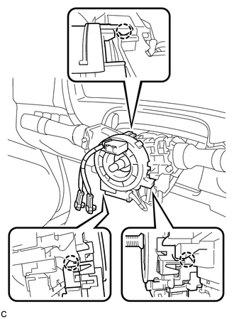
10. REMOVE SPIRAL CABLE WITH SENSOR SUB-ASSEMBLY
NOTICE:
- Do not replace the spiral cable with the battery connected and the ignition switch on (IG).
- Do not rotate the spiral cable with the battery connected and the ignition switch on (IG).
- Ensure that the steering wheel is installed and aligned straight when inspecting the steering sensor.
- Do not remove the steering sensor from the spiral cable.
(a) Disconnect the connectors from the spiral cable with sensor sub-assembly.
NOTICE:
When disconnecting any airbag connector, take care not to damage the airbag wire harness.
|
(b) Disengage the 3 claws to remove the spiral cable with sensor sub-assembly. |
|
 Inspection
INSPECTION
PROCEDURE
1. INSPECT SPIRAL CABLE
(a) Visually check for defects with the spiral cable removed from the vehicle.
(1) The defects are as follows:
Scratches on the spiral cable
...
 Installation
INSTALLATION
PROCEDURE
1. INSTALL SPIRAL CABLE WITH SENSOR SUB-ASSEMBLY
NOTICE:
Do not replace the spiral cable with the battery connected and the ignition
switch on (IG).
Do not r ...
Other materials about Toyota Venza:
Glossary Of Sae And Toyota Terms
GLOSSARY OF SAE AND TOYOTA TERMS
This glossary lists all SAE-J1930 terms and abbreviations used in this manual
in compliance with SAE recommendations, as well as their TOYOTA equivalents.
SAE
Abbreviation
SAE Term
TOYOTA ...
Precaution
PRECAUTION
1. PRECAUTION FOR DISCONNECTING THE BATTERY CABLE
NOTICE:
When disconnecting the cable from the negative (-) battery terminal, initialize
the following systems after the terminal is reconnected.
System Name
See Procedure
...
Customize Parameters
CUSTOMIZE PARAMETERS
1. CUSTOMIZING FUNCTION WITH TECHSTREAM
HINT:
The items in the table below can be customized.
NOTICE:
When the customer requests a change in a function, first make sure that
the function can be customized.
Be sure to m ...

0.131