Toyota Venza: Installation
INSTALLATION
PROCEDURE
1. INSTALL TRANSMISSION CONTROL CABLE ASSEMBLY
NOTICE:
Before installing the transmission control cable assembly, check that the park/neutral position switch and the shift lever are in neutral.
(a) Pass the control cable from the cabin to the engine compartment.
|
(b) Install the No. 2 shift cable grommet retainer with the 2 bolts. Text in Illustration
Torque: 5.0 N·m {51 kgf·cm, 44 in·lbf} |
|
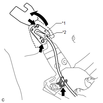
(c) Connect the transmission control cable to the No. 2 transmission control cable bracket.
(d) Before attaching cable to transmission, make sure to pull cable through dash grommet into engine compartment side until cable crimp is fully seated against dash grommet.
|
(e) Connect the transmission control cable to the transmission control shaft lever with the nut. Torque: 13 N·m {130 kgf·cm, 9 ft·lbf} |
|
.png)
(f) Connect the transmission control cable to the transmission control cable bracket with a new clip.
2. INSTALL FRONT NO. 1 FLOOR HEAT INSULATOR
|
(a) Install the front No. 1 floor heat insulator to the body with the 3 nuts. Torque: 4.9 N·m {50 kgf·cm, 43 in·lbf} |
|
.png)
3. INSTALL EXHAUST MANIFOLD TO HEAD GASKET
.gif)
4. INSTALL EXHAUST MANIFOLD SUB-ASSEMBLY RH
5. INSTALL MANIFOLD STAY
6. INSTALL FRONT NO. 3 EXHAUST PIPE SUB-ASSEMBLY
7. INSTALL AIR CLEANER CASE
8. INSTALL AIR CLEANER CAP WITH HOSE
9. INSTALL INLET NO. 2 AIR CLEANER
10. INSTALL COOL AIR INTAKE DUCT SEAL
11. INSTALL INSTRUMENT PANEL REINFORCEMENT ASSEMBLY WITH AIR CONDITIONING UNIT
(See page )
12. INSPECT SHIFT LEVER POSITION
13. ADJUST SHIFT LEVER POSITION
14. INSPECT FOR EXHAUST GAS LEAK
 Adjustment
ADJUSTMENT
PROCEDURE
1. INSPECT SHIFT LEVER POSITION
(a) When moving the lever from P to R with the ignition switch ON and the brake
pedal depressed, make sure that the shift lever moves smoothly ...
 Transmission Wire(when Not Using The Engine Support Bridge)
Components
COMPONENTS
ILLUSTRATION
Installation
INSTALLATION
PROCEDURE
1. INSTALL TRANSMISSION WIRE
(a) Coat the O-ring with ATF.
...
Other materials about Toyota Venza:
Problem Symptoms Table
PROBLEM SYMPTOMS TABLE
HINT:
Use the table below to help determine the cause of problem symptoms.
If multiple suspected areas are listed, the potential causes of the symptoms
are listed in order of probability in the "Suspected Area" ...
Installation
INSTALLATION
PROCEDURE
1. INSTALL TIMING CHAIN COVER SUB-ASSEMBLY
(a) Apply a light coat of engine oil to 2 new oil pump gaskets and new
oil hole cover gasket.
(b) Install the 2 new oil pump gas ...
Camshaft Position "A" - Timing Over-Advanced or System Performance (Bank 1)
(P0011,P0012)
DESCRIPTION
Refer to DTC P0010 (See page ).
DTC No.
DTC Detection Condition
Trouble Area
P0011
The valve timing is stuck at a certain value when in the advance range
(1 trip detection logic).
...

0.1566