Toyota Venza: Transmission Wire(when Not Using The Engine Support Bridge)
Components
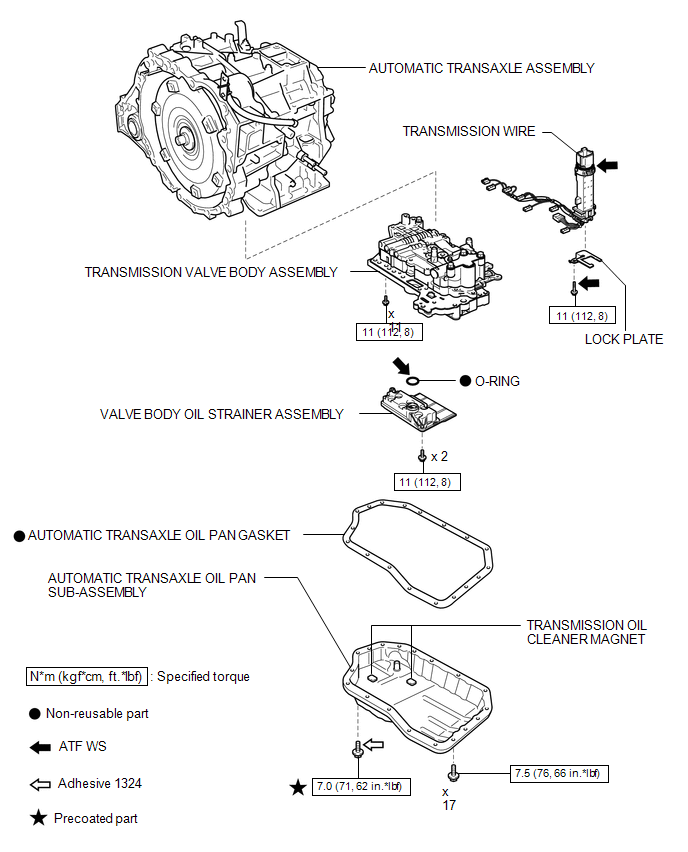
COMPONENTS
ILLUSTRATION
Installation
INSTALLATION
PROCEDURE
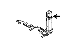
1. INSTALL TRANSMISSION WIRE
|
(a) Coat the O-ring with ATF. |
|
(b) Coat the bolt with ATF.
|
(c) Install the transmission wire and lock plate to the transmission valve body assembly with the bolt. Torque: 11 N·m {112 kgf·cm, 8 ft·lbf} |
|
|
(d) Engage the clamp. |
|
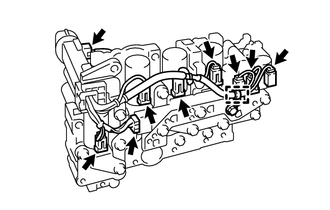
(e) Connect the 8 shift solenoid valve connectors.
(f) Connect the speed sensor connector.
2. INSTALL TRANSMISSION VALVE BODY ASSEMBLY
.gif)
3. INSTALL VALVE BODY OIL STRAINER ASSEMBLY
4. INSTALL AUTOMATIC TRANSAXLE OIL PAN SUB-ASSEMBLY
5. INSTALL AUTOMATIC TRANSAXLE ASSEMBLY
HINT:
See the steps from "Install Automatic Transaxle Assembly" through "Install Engine
Assembly with Transaxle" (See page ).
Removal
REMOVAL
PROCEDURE
1. REMOVE AUTOMATIC TRANSAXLE ASSEMBLY
HINT:
See the steps from "Remove Engine Assembly with transaxle" through "Remove Automatic
Transaxle Assembly" (See page .gif) ).
).
2. REMOVE AUTOMATIC TRANSAXLE OIL PAN SUB-ASSEMBLY
3. REMOVE VALVE BODY OIL STRAINER ASSEMBLY
4. REMOVE TRANSMISSION VALVE BODY ASSEMBLY
5. REMOVE TRANSMISSION WIRE
|
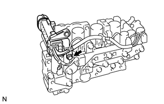
(a) Disconnect the speed sensor connector. |
|
.png)
(b) Disconnect the 8 shift solenoid valve connectors.
(c) Disengage the clamp.
|
(d) Remove the bolt, lock plate and transmission wire from the transmission valve body assembly. |
|
.png)
 Installation
INSTALLATION
PROCEDURE
1. INSTALL TRANSMISSION CONTROL CABLE ASSEMBLY
NOTICE:
Before installing the transmission control cable assembly, check that the park/neutral
position switch and the shift ...
 Transmission Wire(when Using The Engine Support Bridge)
Components
COMPONENTS
ILLUSTRATION
Installation
INSTALLATION
PROCEDURE
1. INSTALL TRANSMISSION WIRE
(a) Coat the O-ring with ATF.
...
Other materials about Toyota Venza:
Precaution
PRECAUTION
NOTICE:
When disconnecting the cable from the negative (-) battery terminal, initialize
the following systems after the cable is reconnected.
System Name
See Procedure
Back Door Closer System
...
System Diagram
SYSTEM DIAGRAM
Transmitting ECU
(Transmitter)
Receiving ECU
Signal
Communication Method
Center Airbag Sensor Assembly
ECM
Crash detection signal
CAN
...
Key battery
Replace the battery with a new one if it is discharged.
- You will need the following items:
• Flathead screwdriver (To prevent damage to the key, cover the tip of the screwdriver
with rag.)
• Small Phillips-head screwdriver
• Lithium battery ...

0.1658