Toyota Venza: Adjusting the settings
- Adjusting the temperature setting
Turn the temperature control dial clockwise (warm) or counterclockwise (cool).
The air conditioning system switches between dual and simultaneous modes each
time  is pressed.
Each temperature setting will be displayed on the multi-information display.
Dual mode: The temperature for the driver’s seat and front passenger’s seats can be set separately.
SYNC mode: Only  (driver’s side)
can be used to adjust the temperature for all seats.
In SYNC mode, only one temperature setting will be displayed on the multi-information display.
- Adjusting the fan speed
Press “∧” (increase) or “∨” (decrease) on
 .
.
The fan speed is shown on the display. (7 levels) Pressing the button while in automatic mode will place the fan speed into manual mode. “AUTO” will turn off, and the fan speed setting will be displayed. The air outlet setting will remain in automatic mode.
Press  to turn the fan off.
The air conditioning system display will go blank to indicate that the system is off. If the system is in outside air mode, some outlet airflow may still exist.
- Changing the air outlets
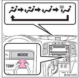
Press  .
.
The air outlets switch each time the button is pressed.
Pressing the button while in automatic mode will place the air outlets into manual mode. “AUTO” will turn off, and the air outlet setting will be displayed. The fan speed setting will remain in automatic mode.
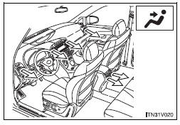
Air flows to the upper body.
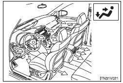
Air flows to the upper body and feet.
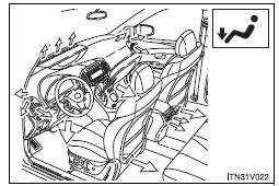
Mainly air flows to the feet.
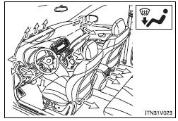
Air flows to the feet and the windshield defogger operates.
- Switching between outside air and recirculated air modes
Press  .
.
The mode switches between outside air mode (indicator off) and recirculated air mode (indicator on) each time the button is pressed.
 Using the automatic mode
Press
.
The air conditioning system will begin to operate. In outside air or recirculated
air mode, air outlets, fan speed and air conditioning on/ off are automatically
adjusted according to ...
 Defogging the windshield
Press .
The air conditioning system control operates automatically.
Recirculated air mode will automatically switch to outside air mode. It is not
possible to return to recirculated air mode wh ...
Other materials about Toyota Venza:
System Description
SYSTEM DESCRIPTION
1. FUNCTION DESCRIPTION
(a) Steering Cooperative Control
(1) Enhanced-VSC performs coordinated control consisting of VSC and electronic
power steering. By integrating these preventive safety functions, Enhanced-VSC ensures
excellent d ...
How To Proceed With Troubleshooting
CAUTION / NOTICE / HINT
HINT:
*: Use the Techstream
PROCEDURE
1.
VEHICLE BROUGHT TO WORKSHOP
NEXT
2.
CUSTOMER PROBLEM ANALYSIS
...
Installation
INSTALLATION
PROCEDURE
1. INSTALL TRANSMISSION CONTROL CABLE ASSEMBLY
NOTICE:
Before installing the transmission control cable assembly, check that the park/neutral
position switch and the shift lever are in neutral.
(a) Pass the control cable from the ...

0.1561