Toyota Venza: Interior Light Power Source Circuit
DESCRIPTION
The main body ECU (driver side junction block assembly) controls operation of the DOME CUT relay in order to supply power to the interior lights.
WIRING DIAGRAM
.png)
CAUTION / NOTICE / HINT
NOTICE:
Inspect the fuses for circuits related to this system before performing the following inspection procedure.
PROCEDURE
|
1. |
INSPECT DOME CUT RELAY |
(a) Remove the DOME CUT relay.
|
(b) Measure the resistance according to the value(s) in the table below. Standard Resistance:
|
|
.png)
| NG | .gif) |
REPLACE DOME CUT RELAY |
|
.gif)
|
2. |
CHECK HARNESS AND CONNECTOR (BATTERY - MAIN BODY ECU (DRIVER SIDE JUNCTION BLOCK ASSEMBLY)) |
(a) Disconnect the 2C main body ECU (driver side junction block assembly) connector.
(b) Measure the voltage according to the value(s) in the table below.
Standard Voltage:
|
Tester Connection |
Condition |
Specified Condition |
|---|---|---|
|
2C-27 - Body ground |
Ignition switch off |
11 to 14 V |
| NG | |
REPAIR OR REPLACE HARNESS OR CONNECTOR |
|
|
3. |
CHECK HARNESS AND CONNECTOR (DOME CUT RELAY - MAIN BODY ECU (DRIVER SIDE JUNCTION BLOCK ASSEMBLY) AND BODY GROUND) |
(a) Disconnect the 2R main body ECU (driver side junction block assembly) connector.
(b) Measure the resistance according to the value(s) in the table below.
Standard Resistance:
|
Tester Connection |
Condition |
Specified Condition |
|---|---|---|
|
Relay Terminal 5 - 2R-6 |
Always |
Below 1 Ω |
|
Relay Terminal 2 - 2R-7 |
Always |
Below 1 Ω |
|
Relay Terminal 5 - Body ground |
Always |
10 kΩ or higher |
|
Relay Terminal 2 - Body ground |
Always |
10 kΩ or higher |
|
Relay Terminal 1 - Body ground |
Always |
Below 1 Ω |
| NG | |
REPAIR OR REPLACE HARNESS OR CONNECTOR |
|
|
4. |
INSPECT MAIN BODY ECU (DRIVER SIDE JUNCTION BLOCK ASSEMBLY) |
(a) Install the DOME CUT relay.
(b) Reconnect the 2C main body ECU (driver side junction block assembly) connector.
|
(c) Reconnect the 2R main body ECU (driver side junction block assembly) connector. |
|
(d) Measure the voltage according to the value(s) in the table below.
Standard Voltage:
|
Tester Connection |
Condition |
Specified Condition |
|---|---|---|
|
2R-6 - Body ground |
Ignition switch off |
11 to 14 V |
|
2R-7 - Body ground |
Ignition switch ON |
11 to 14 V |
|
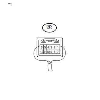
*1 |
Component with harness connected (Main Body ECU (Driver Side Junction Block Assembly)) |
| OK | |
REPAIR OR REPLACE HARNESS OR CONNECTOR (DOME CUT RELAY - EACH LIGHT) |
| NG | |
PROCEED TO NEXT SUSPECTED AREA SHOWN IN PROBLEM SYMPTOMS TABLE |
 Engine Switch Illumination Circuit
DESCRIPTION
The illuminated entry system controls the engine switch illumination.
WIRING DIAGRAM
PROCEDURE
1.
PERFORM ACTIVE TEST USING TECHSTREAM
(a) Connect th ...
 Door Unlock Detection Switch Circuit
DESCRIPTION
The main body ECU (driver side junction block assembly) detects the condition
of the door unlock detection switch.
WIRING DIAGRAM
PROCEDURE
1.
READ VALUE USI ...
Other materials about Toyota Venza:
Winter driving tips
Carry out the necessary preparations and inspections before driving the vehicle
in winter. Always drive the vehicle in a manner appropriate to the prevailing weather
conditions.
- Pre-winter preparations
• Use fluids that are appropriate to the p ...
Installation
INSTALLATION
PROCEDURE
1. INSTALL MANUAL VALVE
(a) Coat the manual valve with ATF and install it to the transmission
valve body assembly.
2. INSTALL TRANSMISSION VALVE BODY ASSEMBLY
(a) Coat th ...
Turn signal lever
1. Right turn
2. Left turn
3. Move and hold the lever partway to signal a lane change.
The right hand signal will flash until you release the lever.
4. Move and hold the lever partway to signal a lane change.
The left hand signal will flash until you re ...

0.1207