Toyota Venza: Components
COMPONENTS
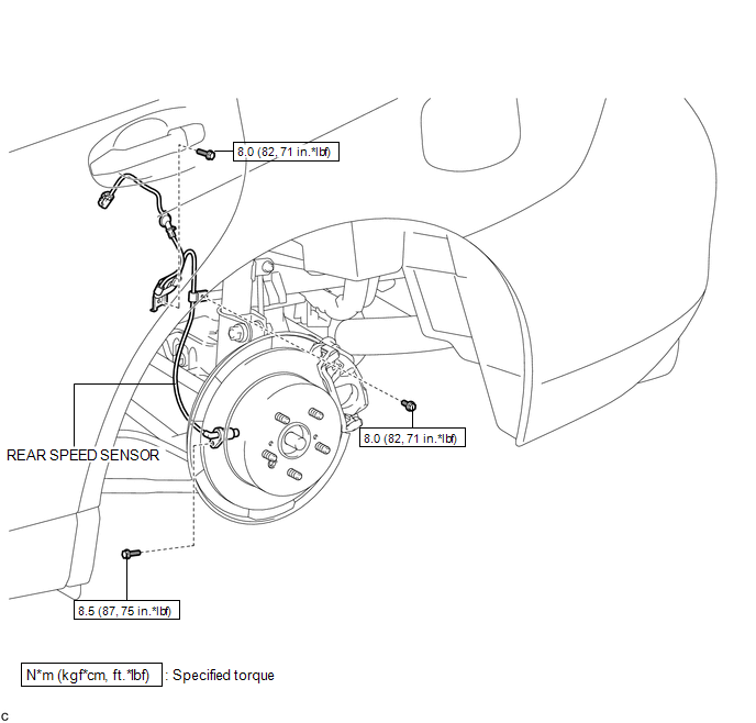
ILLUSTRATION
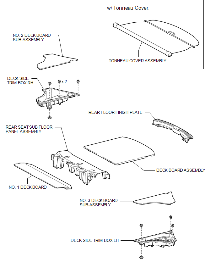
ILLUSTRATION
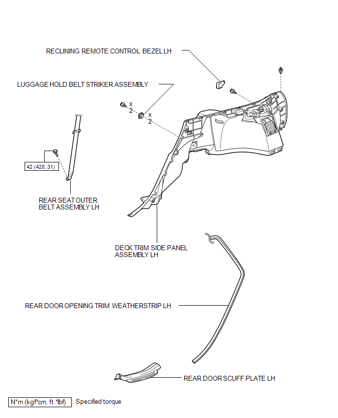
ILLUSTRATION

 Installation
INSTALLATION
CAUTION / NOTICE / HINT
HINT:
Use the same procedure for the LH side and RH side.
The following procedure is for the LH side.
If the sensor rotor needs to be replaced, ...
Other materials about Toyota Venza:
Towing with a wheel lift-type truck
►From the front (2WD models)
Release the parking brake.
►From the front (AWD models)
Use a towing dolly under the rear wheels.
► From the rear
Use a towing dolly under the front wheels. ...
Tire Pressure Warning Receiver
Components
COMPONENTS
ILLUSTRATION
Removal
REMOVAL
PROCEDURE
1. DISCONNECT CABLE FROM NEGATIVE BATTERY TERMINAL
NOTICE:
When disconnecting the cable, some systems need to be initialized after the cable
is reconnected (See page ).
2. REMOVE RO ...
Side doors
The vehicle can be locked and unlocked using the entry function, wireless
remote control, key or door lock switch.
- Entry function (vehicles with smart key system)
- Wireless remote control
- Key
► Vehicles with smart key system ...

0.1455