Toyota Venza: Rear Height Control Sensor (B241A)
DESCRIPTION
The headlight leveling ECU assembly receives signals indicating the height of the vehicle from the rear height control sensor sub-assembly RH.
|
DTC No. |
DTC Detecting Condition |
Trouble Area |
|---|---|---|
|
B241A |
|
|
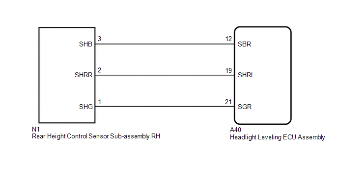
WIRING DIAGRAM
CAUTION / NOTICE / HINT
NOTICE:
If either of the following is performed, initialization of the headlight leveling
ECU assembly is necessary (See page .gif) ).
).
- Replacement of the headlight leveling ECU assembly.
- Replacement or removal/installation of the rear height control sensor sub-assembly or work that changes the vehicle height such as replacement of suspension components.
PROCEDURE
|
1. |
CHECK FOR DTC |
(a) Clear the DTCs (See page ).
(b) Check for DTCs (See page ).
OK:
DTC B241A is not output.
| OK | .gif) |
USE SIMULATION METHOD TO CHECK |
|
.gif)
|
2. |
READ VALUE USING TECHSTREAM |
(a) Connect the Techstream to the DLC3.
(b) Turn the ignition switch to ON.
(c) Turn the Techstream on.
(d) Enter the following menus: Body Electrical / HL Auto Leveling / Data List.
(e) Read the display on the Techstream.
HL Auto Leveling|
Tester Display |
Measurement Item/Range |
Normal Condition |
Diagnostic Note |
|---|---|---|---|
|
Height Sens Pw Supply Val |
Rear height control sensor power supply value / 0.00 to 5.00 V |
Approx. 5 V |
- |
|
Rr Height Sens Signal Val |
Rear height control sensor signal value / 0.00 to 5.00 V |
Approx. 2.5 V (When the vehicle is level) |
Value changes according to vehicle height |
OK:
Normal conditions listed above are displayed.
| OK | |
REPLACE HEADLIGHT LEVELING ECU ASSEMBLY |
|
|
3. |
INSPECT REAR HEIGHT CONTROL SENSOR SUB-ASSEMBLY RH |
(a) Remove the rear height control sensor sub-assembly RH (See page
).
(b) Inspect the rear height control sensor sub-assembly RH (See page
).
| NG | |
REPLACE REAR HEIGHT CONTROL SENSOR SUB-ASSEMBLY RH |
|
|
4. |
CHECK HARNESS AND CONNECTOR (HEADLIGHT LEVELING ECU ASSEMBLY - REAR HEIGHT CONTROL SENSOR RH) |
(a) Disconnect the A40 headlight leveling ECU assembly connector.
(b) Disconnect the N1 rear height control sensor sub-assembly RH connector.
(c) Measure the resistance according to the value(s) in the table below.
Standard Resistance:
|
Tester Connection |
Condition |
Specified Condition |
|---|---|---|
|
A40-19 (SHRL) - N1-2 (SHRR) |
Always |
Below 1 Ω |
|
A40-19 (SHRL) - Body ground |
Always |
10 kΩ or higher |
| OK | |
REPLACE HEADLIGHT LEVELING ECU ASSEMBLY |
| NG | |
REPAIR OR REPLACE HARNESS OR CONNECTOR |
 HL AutoLeveling ECU Failure (B2420)
DESCRIPTION
When the headlight leveling ECU assembly detects a malfunction in itself, this
DTC is stored.
DTC No.
DTC Detecting Condition
Trouble Area
...
 Height Control Sensor Malfunction (B2416)
DESCRIPTION
The DTC is stored when the headlight leveling ECU assembly detects malfunctions
in the rear height control sensor sub-assembly RH power source or rear height control
sensor sub-assemb ...
Other materials about Toyota Venza:
Check CAN Bus Line for Short to +B
DESCRIPTION
There may be a short circuit between the CAN bus main wire and +B when no resistance
exists between terminals 6 (CANH) and 16 (BAT) or 14 (CANL) and 16 (BAT) of the
DLC3.
Symptom
Trouble Area
No resistan ...
System Diagram
SYSTEM DIAGRAM
Communication Table
Sender
Receiver
Signal
Communication Method
Center airbag sensor assembly
Combination meter assembly
Front seat inner belt buckl ...
Installation
INSTALLATION
CAUTION / NOTICE / HINT
HINT:
Use the same procedure for the RH side and LH side.
The procedure listed below is for the LH side.
PROCEDURE
1. INSTALL REAR AXLE CARRIER SUB-ASSEMBLY
(a) Temporarily install the rea ...

0.1719