Toyota Venza: Installation
INSTALLATION
PROCEDURE
1. INSTALL REAR SEAT ASSEMBLY RH
(a) Place the rear seat assembly RH in the cabin.
NOTICE:
Be careful not to damage the vehicle body.
|
(b) Temporarily install the 2 bolts on the front side of the seat. |
|
.png)
|
(c) Temporarily install the 3 bolts on the rear side of the seat. |
|
.png)
(d) Install the rear seat assembly RH with the 5 bolts.
Torque:
37 N·m {377 kgf·cm, 27 ft·lbf}
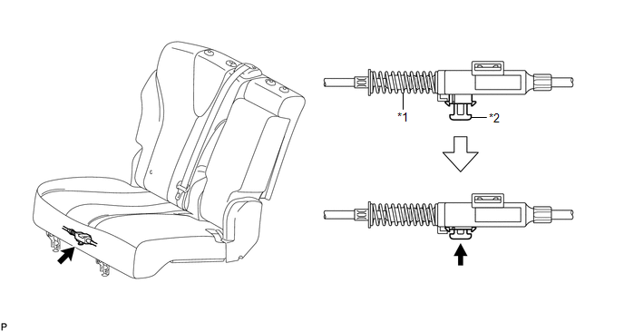
2. CONNECT REAR SEAT RECLINING CONTROL CABLE SUB-ASSEMBLY
(a) Connect the rear seat reclining control cable as shown in the illustration.
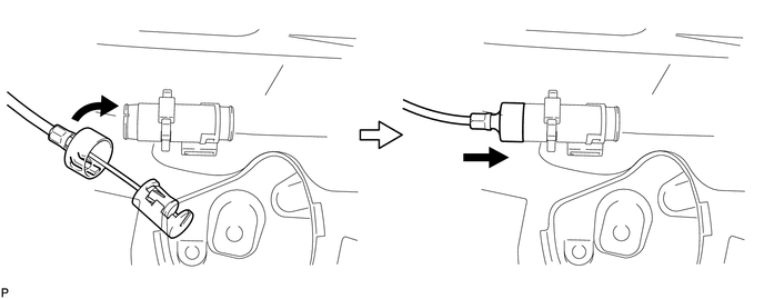
(b) Connect the rear seat reclining control cable sub-assembly as shown in the illustration.
 Text in Illustration
|
*1 |
Protective Tape |
*2 |
Seat Track Adjusting Handle |
|
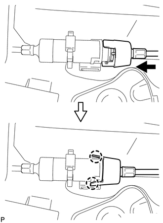
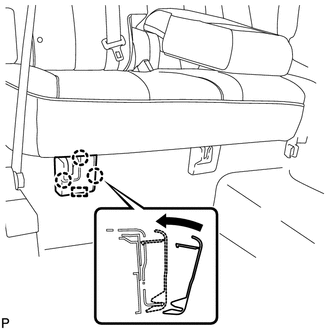
(c) Engage the 2 claws and connect the rear seat reclining control cable sub-assembly as shown in the illustration. |
|
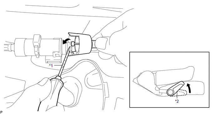
(d) Return the seatback to the upright position.
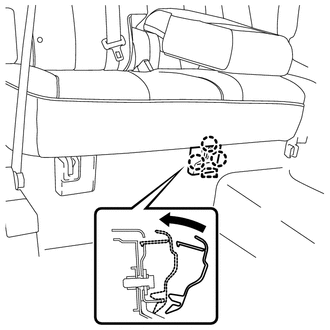
(e) Pull up the adjuster's lock piece to lock it as shown in the illustration.
 Text in Illustration
|
*1 |
Adjuster Spring |
*2 |
Lock Piece |
NOTICE:
When pressing the lock piece, make sure the adjuster's spring is not compressed.
3. INSTALL REAR SEAT OUTER TRACK BRACKET COVER
|
(a) Engage the 3 claws and guide, and install the rear seat outer track bracket cover as shown in the illustration. |
|
4. INSTALL REAR SEAT INNER TRACK BRACKET COVER
|
(a) Engage the 3 claws and guide, and install the rear seat inner track bracket cover as shown in the illustration. |
|
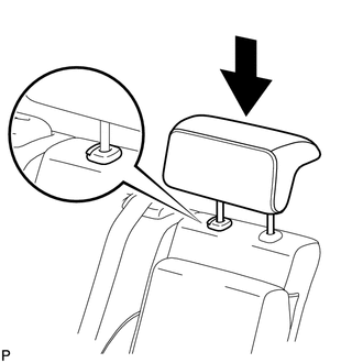
5. INSTALL REAR SEAT CENTER HEADREST ASSEMBLY
|
(a) Install the rear seat center headrest assembly as shown in the illustration. |
|
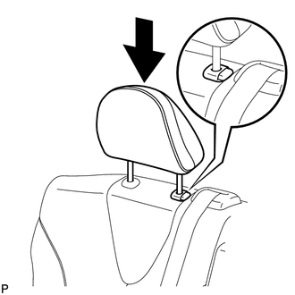
6. INSTALL REAR SEAT HEADREST ASSEMBLY
|
(a) Install the rear seat headrest assembly as shown in the illustration. |
|
 Reassembly
REASSEMBLY
PROCEDURE
1. INSTALL REAR SEAT LEG ASSEMBLY RH
(a) Using a T55 "TORX" socket wrench, install the rear seat leg assembly
RH with the 5 "TORX" bolts.
...
 Seat Heater Control
Components
COMPONENTS
ILLUSTRATION
Installation
INSTALLATION
PROCEDURE
1. INSTALL SEAT HEATER CONTROL SUB-ASSEMBLY
(a) Engage the clamp and install the seat heater control sub- ...
Other materials about Toyota Venza:
Reporting safety defects for U.S. owners
If you believe that your vehicle has a defect which could cause a crash or could
cause injury or death, you should immediately inform the National Highway Traffic
Safety Administration (NHTSA) in addition to notifying Toyota Motor Sales, U.S.A.,
Inc.
(T ...
Transmission Fluid Temperature Sensor "A" Circuit Low Input (P0712,P0713)
DESCRIPTION
The Automatic Transmission Fluid (ATF) temperature sensor converts the fluid
temperature into a resistance value for use by the TCM.
The TCM applies a voltage to the temperature sensor through terminal THO1 of
the TCM.
The sensor resistanc ...
Removal
REMOVAL
CAUTION / NOTICE / HINT
HINT:
Use the same procedure for the LH side and RH side.
The following procedure listed below is for the LH side.
PROCEDURE
1. REMOVE FRONT WHEEL
2. REMOVE FRONT WIPER ARM HEAD CAP
3. REMOVE FRONT WI ...

0.149