Toyota Venza: Removal
REMOVAL
PROCEDURE
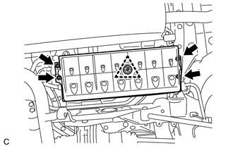
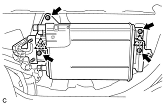
1. REMOVE NO. 1 FLOOR UNDER COVER
(a) Disengage the 4 nuts and clip, and remove the No. 1 floor under cover.
 Text in Illustration
.png) |
Nut (attached to under cover) |
HINT:
Rotate the clip to disengage it. The 4 nuts will remain attached to the No. 1 floor under cover.
2. REMOVE CHARCOAL CANISTER ASSEMBLY
(a) Disconnect the vent line tube from the charcoal canister assembly.
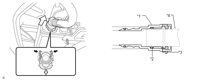 Text in Illustration
|
*1 |
Tube Connector |
*2 |
O-ring |
|
*3 |
Retainer |
*4 |
Pipe (Charcoal Canister Assembly) |
|
|
Pinch |
.png) |
Pull |
NOTICE:
- Remove any dirt or foreign matter on the tube connector before performing this work.
- Do not allow any scratches or foreign matter to get on the parts when disconnecting them as the tube connector has an O-ring that seals the pipe.
- Perform this work by hand. Do not use any tools.
- Do not forcibly bend, twist or turn the vent line tube.
- Protect the disconnected parts by covering them with plastic bags after disconnecting the vent line tube.
- If the tube connector and pipe are stuck, push and pull on them to release.
HINT:
Do not remove the retainer.
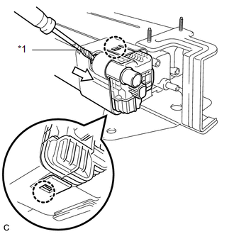
(b) Disconnect the air line tube from the charcoal canister leak detection pump sub-assembly.
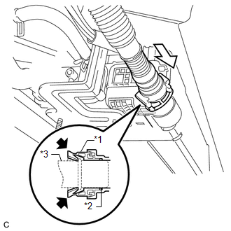 Text in Illustration
|
*1 |
Tube Connector |
|
*2 |
O-ring |
|
*3 |
Pipe (charcoal canister leak detection pump sub-assembly) |
|
|
Pinch |
|
|
Push |
NOTICE:
- Remove any dirt or foreign matter on the tube connector before performing this work.
- Do not allow any scratches or foreign matter to get on the parts when disconnecting them as the tube connector has an O-ring that seals the pipe.
- Perform this work by hand. Do not use any tools.
- Do not forcibly bend, twist or turn the air line tube.
- Protect the disconnected parts by covering them with plastic bags after disconnecting the air line tube.
- If the tube connector and pipe are stuck, push and pull on them to release.
(1) Push the air line tube firmly toward the charcoal canister assembly side.
(2) Pinch the tube connector as shown in the illustration.
(3) Pull out the air line tube.
|
(c) Disconnect the purge line hose from the charcoal canister assembly. |
|
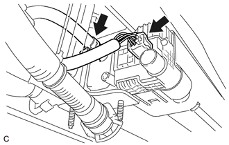
(d) Disconnect the connector from the charcoal canister leak detection pump sub-assembly.
|
(e) Remove the 4 nuts. |
|
(f) Separate the 2 clips from the body to remove the charcoal canister assembly.
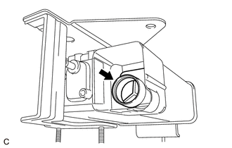
3. REMOVE CHARCOAL CANISTER LEAK DETECTION PUMP SUB-ASSEMBLY
(a) Before removing the charcoal canister leak detection pump sub-assembly, clean the canister by blowing air into it to ensure that the canister is free of foreign matter.
NOTICE:
- Make sure to clean the canister using only air.
- Do not use gasoline, thinners or solvents.
|
(b) While disengaging the 2 claws as shown in the illustration, push the charcoal canister leak detection pump sub-assembly out using a screwdriver to remove it. Text in Illustration
HINT: Tape the screwdriver tip before use. |
|
(c) Check if the canister contains foreign matter such as mud or water.
|
(1) Visually check that the inside of the canister is free of foreign matter. |
|
(2) Hold the canister upside down to make sure that the canister is free of foreign matter.
If the canister contains foreign matter, replace the canister.
 Components
COMPONENTS
ILLUSTRATION
...
 Inspection
INSPECTION
PROCEDURE
1. INSPECT CHARCOAL CANISTER ASSEMBLY
(a) Visually check the charcoal canister assembly.
(1) Visually check the charcoal canister assembly for cracks or damage.
...
Other materials about Toyota Venza:
Panel Switches do not Function
PROCEDURE
1.
CHECK PANEL SWITCH
(a) Check for foreign matter around the switches that might prevent operation.
OK:
No foreign matter is found.
NG
REMOVE ANY FOREIGN MATTER FOUND
...
Installation
INSTALLATION
PROCEDURE
1. INSTALL STEERING PAD
(a) Check that the ignition switch is off.
(b) Check that the cable is disconnected from the negative (-) battery terminal.
CAUTION:
Wait at least 90 seconds after disconnecting the cable from the negative ( ...
Height Control Sensor Data Out of Range When Initializing (B2452)
DESCRIPTION
The headlight leveling ECU assembly stores this DTC if the sensor value received
from the height control sensor is out of range when performing initialization of
the headlight leveling ECU assembly; for example, the vehicle is not level or bei ...

0.1275