Toyota Venza: Removal
REMOVAL
PROCEDURE
1. PRECAUTION
(See page .gif) )
)
NOTICE:
After turning the ignition switch off, waiting time may be required before disconnecting
the cable from the negative (-) battery terminal. Therefore, make sure to read the
disconnecting the cable from the negative (-) battery terminal notices before proceeding
with work (See page ).
2. DISCONNECT CABLE FROM NEGATIVE BATTERY TERMINAL
NOTICE:
When disconnecting the cable, some systems need to be initialized after the cable
is reconnected (See page ).
3. REMOVE UPPER CONSOLE PANEL SUB-ASSEMBLY (w/o Seat Heater System)
4. REMOVE UPPER CONSOLE PANEL SUB-ASSEMBLY (w/ Seat Heater System)
5. REMOVE NO. 2 CONSOLE BOX CARPET
6. REMOVE CONSOLE BOX ASSEMBLY
7. REMOVE AIR CONDITIONING CONTROL ASSEMBLY
8. REMOVE FRONT DOOR SCUFF PLATE RH
9. REMOVE COWL SIDE TRIM SUB-ASSEMBLY RH
10. REMOVE NO. 2 INSTRUMENT PANEL UNDER COVER SUB-ASSEMBLY
11. REMOVE LOWER INSTRUMENT PANEL SUB-ASSEMBLY
12. REMOVE SHIFT LEVER KNOB SUB-ASSEMBLY
13. REMOVE POSITION INDICATOR HOUSING ASSEMBLY
14. REMOVE CONSOLE BOX SUB-ASSEMBLY
15. REMOVE NO. 2 INSTRUMENT PANEL SPEAKER PANEL SUB-ASSEMBLY
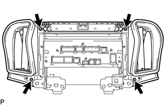
16. REMOVE NAVIGATION RECEIVER ASSEMBLY WITH BRACKET
|
(a) Remove the 4 bolts. |
|
.png)
(b) Disengage the 2 clips.
(c) Disconnect each connector and remove the navigation receiver assembly with bracket.
17. REMOVE INSTRUMENT CLUSTER CENTER FINISH PANEL SUB-ASSEMBLY
|
(a) Remove the 4 screws. |
|
|
(b) Disengage the 4 claws and remove the instrument cluster center finish panel sub-assembly. |
|
.png)
18. REMOVE STEREO COMPONENT TUNER ASSEMBLY WITH WIRE (w/ Satellite Radio)
19. REMOVE NO. 1 RADIO RECEIVER BRACKET
|
(a) Remove the 4 screws and No. 1 radio receiver bracket. |
|
.png)
20. REMOVE NO. 2 RADIO RECEIVER BRACKET
|
(a) Remove the 4 screws and No. 2 radio receiver bracket. |
|
.png)
21. REMOVE NAVIGATION RECEIVER ASSEMBLY
 Components
COMPONENTS
ILLUSTRATION
ILLUSTRATION
ILLUSTRATION
ILLUSTRATION
...
 Installation
INSTALLATION
PROCEDURE
1. INSTALL NAVIGATION RECEIVER ASSEMBLY
2. INSTALL NO. 2 RADIO RECEIVER BRACKET
(a) Install the No. 2 radio receiver bracket with the 4 screws.
Torque:
5.0 N·m {51 kgf· ...
Other materials about Toyota Venza:
Diagnosis System
DIAGNOSIS SYSTEM
1. CHECK BATTERY VOLTAGE
Standard voltage:
11 to 14 V
If the voltage is below 11 V, recharge the battery before proceeding to the next
step.
2. CHECK DLC3
(a) The ECU uses ISO 15765-4 for communication. The terminal arrangement of the ...
Seat heaters
1. For driver’s seat
2. For front passenger’s seat
3. On
The indicator light comes on.
4. Adjusts the seat temperature
The further you turn the dial upward, the warmer the seat becomes.
- The seat heaters can be used when
►Vehicles wit ...
Installation
INSTALLATION
PROCEDURE
1. INSTALL TIMING CHAIN COVER SUB-ASSEMBLY
(a) Apply a light coat of engine oil to 2 new oil pump gaskets and new
oil hole cover gasket.
(b) Install the 2 new oil pump gas ...

0.1182